
The International Data Corporation (IDC) predicts that there will be over 40 billion connected devices by 2025: up from the 31 billion today. Most connected things will do so over wireless. The key feature of wireless systems are antennas and the interfacing RF interconnects. If chosen correctly, antennas lead to high performance wireless devices. However, when overlooked, it can lead to system bottlenecks and instability. When considering your antenna choice, there are four factors that should be considered and are addressed below.
1. What is the intended use?
2. Wireless standard or custom build?
3. Impedance matching
4. VSWR
1. What is the intended use?
When choosing antennas, the questions that needs to be answered are where and how the antenna will be used. If an application requires maximum range and signal strength, then an external antenna would be ideal. For all other applications, an internal antenna can be used and tuned accordingly to section 2.
2. Wireless standard or custom build?
The table below shows the wide array of wireless standards provided by Suntsu.
For custom build inquiries please contact our Sales & Engineering team.
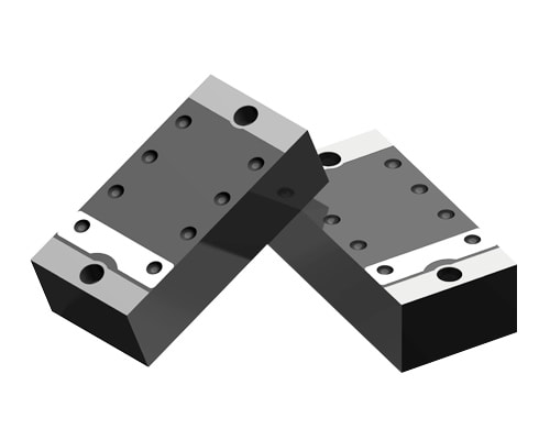
Suntsu Chip Antennas
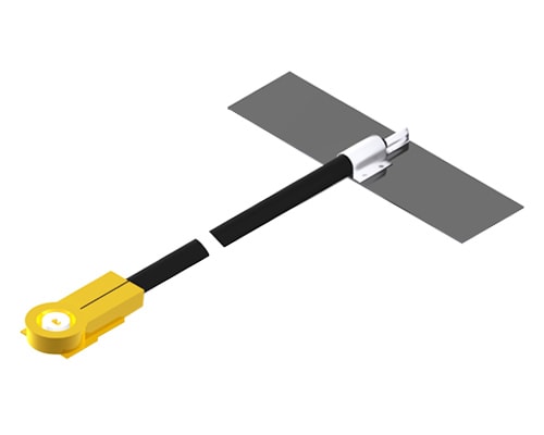
Suntsu PCB Antennas
Suntsu Indoor Antennas
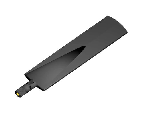
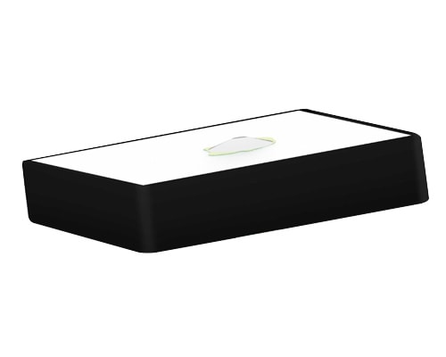
Suntsu Outdoor Antennas
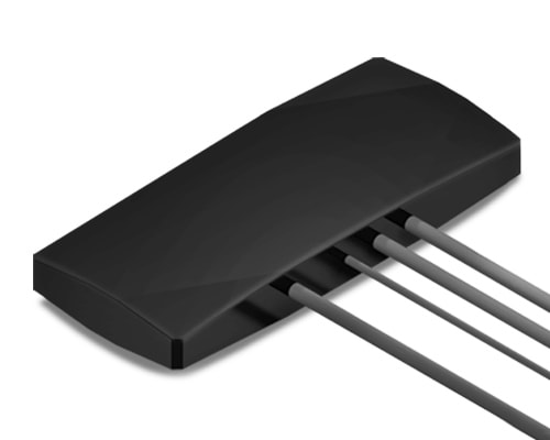
Suntsu Patch Antennas
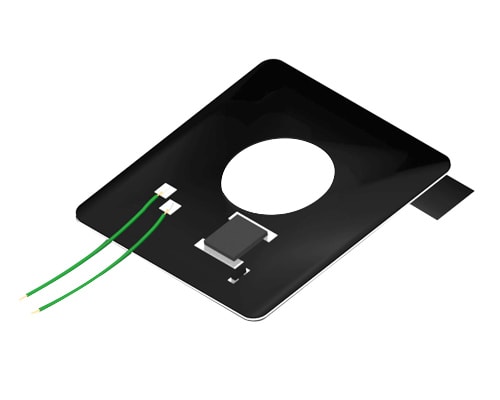
Suntsu NFC Antennas
| Frequency Ranges (MHz) | Antenna Type | Applications | |||||
|---|---|---|---|---|---|---|---|
| Chip | PCB | Indoor | Outdoor | Patch | NFC | ||
| 13.56 | – | – | – | – | – | X | NFC |
| 13.4 | – | – | – | – | – | X | |
| 14.17 | – | – | – | – | – | X | |
| 14.2 | – | – | – | – | – | X | |
| 14.23 | – | – | – | – | – | X | |
| 433 | – | X | – | – | – | – | ISM |
| 433-434.79 | X | – | – | – | – | – | |
| 433.05-434.79, 450-470 | X | – | – | – | – | – | |
| 433.05-434.79, 863-870, 902-928 | X | – | – | – | – | – | |
| 863-870 | X | X | – | – | – | – | |
| 863-870, 902-928 | X | – | – | – | – | – | |
| 902-928 | X | X | – | – | – | – | |
| 689-960, 1710-2690MHz | – | – | X | – | – | – | Cellular |
| 698-960, 1710-2170, 2300-2400, 2490-2690 | – | X | – | – | – | – | |
| 698-798, 824-960, 1710-2170, 2300-2400, 2490-2690 | X | – | – | – | – | – | |
| 824-960, 1710-2170 | X | X | – | – | – | – | |
| 824-960, 1710-2170, 2400-2500 | – | X | – | – | – | – | |
| 824-960, 1710-2170, 2400-2500, 2490-2690 | – | X | – | – | – | – | |
| 746-960, 1710-2170MHz | – | – | X | – | – | – | |
| 704-960, 1427.9-1575.42, 1710-2170, 2400-2690 | – | – | X | – | – | – | |
| 698-960, 1427.9-1510.9, 1559-1610, 1695-2200, 2300-2700 & 3400-3600MHz | – | X | X | – | – | - | |
| 1560-1606 | X | – | – | – | – | – | GPS / Glonass |
| 1575.42 | X | – | – | – | – | – | |
| 1575.42, 2400-2500 | X | – | – | – | – | – | |
| 1575.42, 2400-2500,5150-5850 | X | – | – | – | – | – | |
| 1575.42MHz & 1598~1606MHz, | – | – | – | – | X | – | |
| 2400-2500 | X | X | X | X | – | – | WiFi |
| 2400-2500, 4900-5900 | – | X | – | – | – | – | |
| 2400-2500, 5150-5850 | X | – | X | – | – | – | |
| 5150-5850 | – | – | – | – | – | – | |
| 5150-5900 | X | X | – | – | – | – | |
| 2400-2500, ground plane 80*40 | – | – | – | – | – | – | |
| 1880-1930 | X | – | – | – | – | – | DECT |
| GPS + GSM + WiFi (1575.42MHz, 2.4GHz, 824~960, 1710~2170) | – | – | – | X | – | – | GPS + LTE + WiFi |
| GPS + LTE + WiFi (1575.42MHz, 698~960MHz, 1710~2690MHz, 2.4GHz, 5.0GHz) | – | – | – | X | – | – | |
| Dual band WIFI (2400~2483.5, 4900~5825MHz) | – | – | – | – | – | – | |
| GPS + LTE + WiFi (698-960MHz, 1710-2700MHz, 2400-2484MHz, 5150-5850MHz) | – | – | – | X | – | – | |
| GPS + LTE (1572-1610MHz, 698-960MHz, 1710-2690MHz | – | – | – | X | – | – | |
3. Impedance matching
Successful impedance matching allows for maximum power transfer and minimal signal reflection from the load. Therefore, if the cable, connectors, and antenna all have matching impedance levels, they will be able to deliver the maximum power, resulting in greater efficiency throughout the system.
External antenna = Antenna + RF Cable + Connector
PCB antenna = Antenna + Connector
Chip antenna = N/A (soldered directly on the board)
4. VSWR
VSWR (Voltage Standing Wave Ratio) is a measurement of efficiency. It looks at how efficiently power is sent from a power source to the load. It can be measured with the calculation VMAX/VMIN where VMAX is Maximum Voltage and VMIN is Minimum Voltage. The lower the VSWR the more efficient the power distribution across the system. Although it is important for an antenna to have a low VSWR value, this becomes irrelevant if it is not matched to the rest of the system. A system operates at the speed and efficiency of its weakest link. Therefore, if the cable and connector do not have matching or lower VSWR ratings as the antenna, then the system will not operate at the antenna’s rated VSWR.
A combination of these factors translates to a better performing and more balanced system.
Contact us if you would like to learn more.

Sourcing/Manufacturing

Inventory Management

Engineering Services
Helping Tech Companies Create What’s Next!
We help our customers build better products, save time, save money, and improve cash-flow/lead-times through inventory management programs.
