In certain oscillator applications, controlling how the oscillator operates is crucial. These modes can be undesirable, like harmonic, resonant, or spurious modes, or they can be standard modes like fundamental, third overtone, or fifth overtone. Undesired modes typically have higher frequencies than desired modes, sometimes within a few hundred kHz. When using pull-able crystals, large electrodes are needed on the blank’s surface, which can lead to spurs and cause the crystal to oscillate in a spurious mode. Undesirable modes are usually specified in resistance or the ratio of the undesired mode’s resistance to the desired mode’s resistance across a frequency range. A 3dB separation between the desired and undesired modes is usually sufficient to prevent spurious mode operation.
Methods for controlling fundamental modes in third overtone circuits
- Inductor-less third overtone circuit (diagram A): This resembles a fundamental mode circuit, but the feedback resistor value is much smaller. This smaller resistor makes the inductive admittance component larger than the load capacitance admittance at the fundamental frequency, preventing oscillation. At the overtone, the inductive admittance is less than the load capacitance admittance, allowing oscillation at the third overtone.
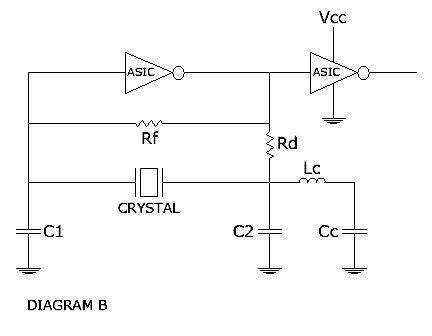
- Tuning tank L/C overtone circuit (diagram B): This circuit adds an inductor and capacitor to select the third overtone mode and suppress the fundamental mode. The inductance and capacitance values must meet the following conditions:
- The Lc/Cc section creates a series resonant circuit at a frequency below the fundamental, making the circuit appear inductive at the fundamental frequency. This discourages oscillation at the fundamental mode.
- The Lc/Cc and C2 components form a parallel resonant circuit at a frequency roughly halfway between the fundamental and third overtone frequencies. This makes the circuit capacitive at the third overtone frequency, favoring oscillation at that mode.
- Ideally, the Lc tank is placed at the inverter’s output to filter out unwanted modes before the signal reaches the crystal.
Need more information?
You can download a PDF version of these notes here, reach out to us by phone at (949) 783-7300 or through our online contact form.


