
Suntsu Patch Antennas offer GPS and GLONASS communications serving the Smart grid, IOT, Enterprise, Automotive, Telecommunications, and Consumer Wireless Industries. We offer frequencies 1575.42MHz and 1598-1606MHz. With package sizes from 15.0×15.0×4.0mm to 25.0×25.0×4.0 mm. Pick out a standard part number from the data sheets listed below or contact us to request any custom parameters or physical modifications that you may desire and we will design to your specific needs.

Microstrip Patch Antennas
| Part Number | Image | Package (mm) | Frequency Band (MHz) | Type | Application | Datasheet |
|---|---|---|---|---|---|---|
| SATPA-15A15A4A-GPB7 |  | 15 x 15 x 4 | 1575.42 & 1598-1606 | GPS | GPS/GLONASS | |
| SATPA-15A15A4A-GPB8 | 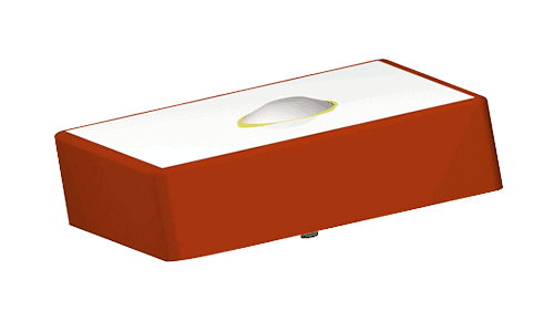 | 15 x 15 x 4 | 1575.42 & 1598-1606 | GPS | GPS/GLONASS | |
| SATPA-18F18F4A-GPB9 | 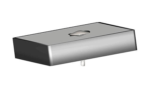 | 15 x 15 x 4 | 1575.42 & 1598-1606 | GPS | GPS/GLONASS | |
| SATPA-25A25A4A-GPB7 | 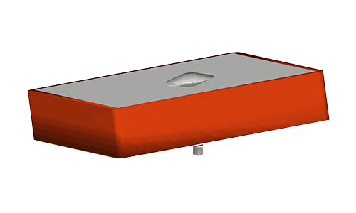 | 25 x 25 x 4 | 1575.42 & 1598-1606 | GPS | GPS/GLONASS |
What is a Patch Antenna?
A patch antenna is a small antenna (low form) that you can mount on a flat sheet rather like a sticker. The complete antenna consists of a patch of metal mounted on a larger piece of metal. The larger piece is the ground plane, and the two sheets together create a microstrip transmission line. The patch antenna radiation arises from the edges, and this effect creates a flat patch antenna electrically larger than its physical dimensions indicate.
How Does a Patch Antenna Work?
The metal ground and the metal patch are separated. Typically, by photoetching the patch onto a dielectric substrate. A substrate provides mechanical support for the antenna trace, and the right material enhances performance. The separation is necessary to create a resonating circuit. The ground plane must extend beyond the patch’s edges by two or three times the board thickness to ensure that the microstrip antennas work as expected. The distance between the metal patch and the underlying ground plane sets the bandwidth of the radio frequencies the patch antenna can transmit and receive. The shape of the metal patch influences the shape of the electromagnetic radiation field. Power reaches the antenna through a feed line, and the EM waves radiate from the antenna’s width edge. A patch antenna is inefficient at transforming the power supplied into EM radiation. A WiFi patch antenna can only cover a small area like an office, or a shop floor compared to a more efficient antenna covering whole buildings or outdoor spaces.
What are the Uses of Patch Antenna?
You can find patch antennas in every field because they are easy to make and occupy a small amount of space. Typical applications include:
- Military applications include guided missiles, radar, electronic sensing, and tracking people.
- Digital broadcast and receiving of television and signals – for a campus or office-only channel.
- Mobile systems – if you want to move it and communicate with it, a patch antenna is the answer.
- Satellite communication for GPS and other applications uses patch antenna in the satellites and devices.
- Radiofrequency identification (RFID) systems for logistics, healthcare, and manufacturing.
- Arrays of patch antenna create complex antenna useful for MIMO applications with the increased data flow.
- Vehicle collision avoidance systems – a civilian use of electronic sensors to highlight hazards.
- Biological imaging – noninvasive microwave images can detect and visualize brain tumors along with other medical uses.
- Remote sensing for exploring soil moisture levels or the salinity of the sea using satellites or aircraft.
- Tracking people and animals for search and rescue or conservation through collecting information through satellite tags.
Patch antenna uses are increasing, and any application that involves communicating wirelessly uses antennas. Small form patch antennas allow smaller devices and more exciting benefits from technology.
What are the different types and shapes of patch antennas?
A slot is the edge of the patch antenna that transmits and receives the radio signal. The shape of the antenna and the number of slots available dictate how a patch antenna performs. The slot length is half the radio waves’ wavelength, and the bandwidth is narrow – around 1%.
The standard shape of a rectangular patch works effectively for most applications. Still, you can have circular, hexagonal, triangular, and other geometric shapes for the patch and the ground plane. The simple fabrication process results in experimental designs in producing arrays of antenna. For example, a circular patch with two, three, or six slots cut into the shape to create additional radiating and receiving points puts many antennae in a small space.
Patch antenna types include:
- Linear patch antenna tends to be receiving antenna working with the linear whip antennae you find on remote control cars, boats, and model planes.
- Dual-band patch antennas operate on two frequencies (simultaneously or independently), usually 2.4GHz and 5GHz bands for WiFi and mobile phone applications.
- A cellular patch antenna gives a higher directional gain, aiming at a cellular tower. Typically, these are relatively large in scale and pole mounted.
- 2.4 GHz Patch antenna is tuned to receive and send transmissions in the 2.4 GHz band. This is the longer WiFi wavelength capable of penetrating walls.
- GPS active patch antenna is the best performing type for mobile applications. A particular dielectric ceramic substrate supports the antenna patch trace.
- A mini patch antenna is small and light for when both size and weight are an issue. The hobby market makes extensive use of these.
Their shape, characteristics, and performance define patch antennas; most names for these microstrip antennas focus on what they can do and how they perform. A patch antenna calculator calculates the patch’s actual length through a series of calculations involving the Resonance Frequency, relative Permittivity of the dielectric substrate, speed of light, and the height of the substrate. You calculate width and length because a patch antenna is larger than its physical dimensions in electrical performance.
https://www.everythingrf.com/rf-calculators/microstrip-patch-antenna-calculator
Patch Antenna Advantages and Disadvantages
A microstrip or patch antenna is a low-profile antenna with many advantages compared with other antennas:
- Lightweight – wearable and mobile devices need to reduce weight where possible, especially in aerospace applications.
- Inexpensive – when the military developed microstrip antennas, the cost didn’t matter, but commercial applications are price sensitive.
- Integrates well with other electronics – including LNA (Low Noise Amplifiers) and SSPA (Solid State Driver Amplification).
- Versatile to deploy as you can wrap around a curved surface (missile guidance), but usually flat and referred to as planar antennas.
- Creating a patch antenna is a straightforward production process with a high degree of accuracy and little wastage.
- Dual and triple frequency operations in patch antenna design mean you can have multiple applications from a small component.
- Unique pattern creation (EM radiation) by creative and innovative use of arrays of patch antenna beyond a single element’s scope.
Disadvantages:
- Antenna efficiency is low compared to other antennas as only a small fraction of the power converts to radio waves.
- A patch antenna is highly sensitive to environmental factors like temperature and humidity – specification explains tolerances.
- Patch antenna can handle low amounts of power, and they have low gain. This makes them unsuitable for some applications.
- Spurious feed radiation from secondary effects can be an issue, but most patch antenna designs minimize this possibility.
- More dielectric and conductor losses compared with other types of antenna.
- Patch antenna structures mean they operate on a narrow bandwidth (1%), where mobile applications typically need 8% bandwidth.
Frequently Asked Questions
What is the Patch Antenna’s Radiation Pattern?
The patch antenna's radiation pattern is perpendicular to the substrate, and its classes as broad, with low radiation power and narrow bandwidth. The radiation pattern of an antenna reflects the capacity of an antenna to transmit and receive data. The patch antenna design will load the radiation direction either to the front or back of the patch – the preference is to have most of the radiation front-loaded. You achieve an omnidirectional patch antenna using an array of antennas for equal transmission and reception in all directions. Other radiation patterns involve changing patch shapes and geometry, but the purpose is to control the radiation pattern direction, so signals transmit and receive effectively for any given application.
What is a Microstrip Antenna?
A microstrip antenna is a patch antenna, and the terms are interchangeable. Between these two terms, you get various physical structures, and an alternative name is a printed antenna. A patch antenna is effectively a 2D structure that is easy to make as a standalone component or part of a circuit board.
What are Patch Antenna Gain and Polarization?
The gain in antenna terms is the ratio of radiation power in a direction compared to the radiation power in that direction of an isotropic antenna. An isotropic antenna is an imaginary antenna that can radiate equally in all directions. The power gain of an isotropic antenna is 1. A high-gain antenna is beneficial when you know where your signal is coming from – TV broadcast towers, for example. For most wireless applications, a low gain antenna close to the ideal omnidirectional patch antenna is preferable. Polarization is either linear or circular and refers to the plane in which the electric field operates. Satellite applications need circular polarization because it is not impacted by antenna orientation. Part of patch antenna design involves creating the appropriate polarization for the application. Applications that rely on knowing the antenna orientation are suitable for linear patch antenna; otherwise, circular polarization gives an omnidirectional patch antenna suitable for most other applications.
How do I Improve the Gain and Efficiency of a Patch Antenna?
The other part of gain is the antenna's efficiency at turning radio waves into electrical signals, and increasing gain to increase efficiency is a goal in patch antenna design. You can increase the gain (and efficiency) in a patch antenna by turning the substrate into a reflector, rounding corners on the unit, and using an array of antenna instead of a single linear patch antenna.