![]()
SXT5G2 Series – 5.0MM X 3.2MM Glass Sealed SMD 2 Pad Crystal
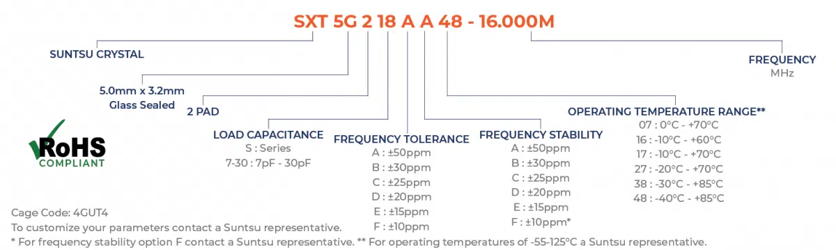
Part Numbering Guide
Electrical Parameters
| Parameters | Units | Min | Typical | Max | Remarks |
|---|---|---|---|---|---|
| Frequency Range | MHz | 8 | 54 | AT-Cut Fundamental. | |
| Frequency Tolerance at +25ºC | ppm | -10 | +10 | See part numbering guide for options. | |
| Frequency Stability vs. Op Temp | ppm | -10 | +10 | See part numbering guide for options. | |
| Frequency Stability vs. Aging | ppm | -3 | +3 | First year @ +25ºC. | |
| Operating Temperature | °C | -40 | +85 | ||
| Storage Temperature | °C | -40 | +125 | See part numbering guide for options. | |
| Load Capacitance | pF | 7 | 30 | See part numbering guide for options. | |
| Shunt Capacitance | pF | 7 | |||
| Drive Level | μW | 100 | 300 | ||
| Insulation Resistance | MΩ | 500 | @ 100VDC ± 15V. | ||
| Equivalent Series Resistance | |||||
| 8.000MHz ~ 11.999MHz | Ω | 100 | AT-Cut Fundamental | ||
| 12.000MHz ~ 19.999MHz | Ω | 80 | AT-Cut Fundamental | ||
| 20.000MHz ~ 29.999MHz | Ω | 70 | AT-Cut Fundamental | ||
| 30.000MHz ~ 54.000MHz | Ω | 50 | AT-Cut Fundamental | ||
| 40.000MHz ~ 100.000MHz | Ω | 70 | 3rd Overtone |
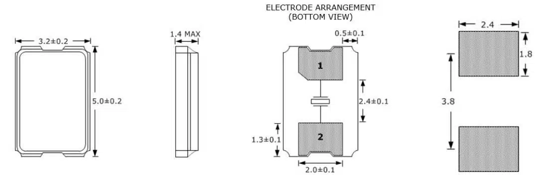
Outline Drawing & Recommended Landed Pattern
All dimensions are in millimeters (mm) unless otherwise noted. Drawings are not to scale.