
Ensure Timing Precision in Your Next Design
Even the most innovative hardware is only as reliable as its clock signal. Our team provides the expert guidance and high-quality components you need to eliminate system-level timing failures.
Unpacking the Noise: Phase Noise, Jitter, and Stability
A common misconception in hardware design is to treat phase noise, jitter, and frequency stability as the same. Although they all refer to issues in the clock signal, they are actually distinct measurements of timing irregularities.
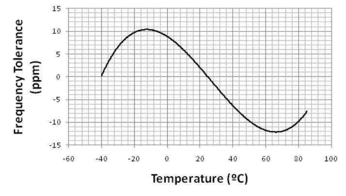
- Frequency Stability: As discussed, this is a broad, long-term metric. It assesses how the fundamental frequency fluctuates over minutes, days, or years because of environmental variations.
- Phase Noise: This metric is a microscopic, short-term measurement in the frequency domain that gauges the quick, random variations in the waveform’s phase. In RF and wireless contexts, phase noise is vital because it can interfere with nearby channels or decrease a receiver’s sensitivity.
- Jitter: Jitter and phase noise both describe timing irregularities but measure different things. Phase noise measures random phase fluctuations in the frequency domain, while jitter measures the deviation of clock edges in the time domain. RMS jitter can be calculated from integrated phase noise over a defined offset frequency range.
To grasp the mathematics and measurement methods underlying these time-domain fluctuations, refer to Clock Jitter Explained: Guide to System Timing Precision.
To summarize these crucial distinctions, consider the following comparison:
Metric Domain Description Primary System Impact Frequency Stability Macroscopic / Long-Term Deviation from nominal frequency over temperature and time. Loss of synchronization between separate systems. Phase Noise Frequency Domain (Short-Term) Random phase fluctuations represented as a noise skirt around the carrier. Degraded RF signal-to-noise ratio; adjacent channel interference. Jitter Time Domain (Short-Term) Variations in the precise timing of the clock edges. Misaligned data sampling; bit errors in digital processors.
When your design demands extreme time-domain accuracy, consider Eliminate Jitter with Suntsu’s Ultra-Low Jitter Oscillators to maintain data integrity across intricate PCB traces.
System-Level Consequences: Data Loss in High-Speed Networks
Poor timing components can have effects that go beyond a single PCB, potentially damaging entire communication systems. But what is the exact way an unstable oscillator leads to data loss?
In high-speed, synchronous data networks, receivers depend on a locally generated clock to precisely sample the incoming data stream of zeros and ones. This data creates an “eye diagram,” which helps visualize signal stability. The receiver must trigger its sampling exactly at the widest and most stable part of this “eye.”
If the local oscillator has poor stability or too much jitter, the sampling window can shift. As a result, the receiver may sample during a voltage transition, such as when the signal changes from 0 to 1, rather than capturing the data bit securely at the eye’s center.
- Bit Error Rate (BER) Spikes: Misaligned sampling causes the receiver to misinterpret the data, drastically increasing the BER.
- Packet Drops: When the BER exceeds the threshold of the system’s forward error correction (FEC) algorithms, entire data packets are deemed corrupted and are subsequently dropped.
- Network Congestion: Dropped packets force the system to request re-transmissions. This consumes valuable bandwidth, increases latency, and degrades the overall throughput of the network.
This level of precision is particularly vital in telecommunications, where handling Frequency Control in the 5G Era demands extraordinary synchronization to avoid data collisions and dropped calls in dense cell networks.
Elevate Your Designs with Suntsu’s Engineering Expertise
At Suntsu Electronics, our role extends beyond just fulfilling orders; we support your innovation. Navigating technical challenges and ensuring a dependable supply chain calls for a strategic partner who grasps both the micro-level physics of frequency control and the broader needs of global manufacturing.
Our dedicated engineering team offers support with design options, obsolescence management, and custom component development to make sure your designs are practical, durable, and free from delays. If you’re having trouble meeting timing requirements or dealing with supply chain issues, check out our Engineering Design Services to see how we can assist in building better products and securing the necessary parts for success.
Our engineering team is ready to help you overcome your toughest timing challenges with design alternatives and custom component solutions. Contact us today to ensure your next project achieves maximum reliability and performance.
FAQs
Smaller packages often face greater manufacturing constraints and can be more susceptible to thermal gradients. While modern silicon technology has improved performance in miniature formats, larger packages generally offer more room for the crystal blank, which can provide better physical stability against environmental stressors.
The choice depends entirely on your product’s deployment environment. Consumer electronics often use 0°C to +70°C, while industrial or automotive applications typically require an industrial range of -40°C to +85°C to ensure system reliability.
Oscillators are subject to aging even when not in use. Proper storage in a controlled environment—avoiding extreme humidity and temperature—is critical to preventing contamination or stress-induced frequency drift before the component is even soldered onto a board.
For most commercial or industrial applications, “recalibration” is not practical in the field. The best strategy is to select an oscillator with an aging specification that meets your total project lifecycle requirements, such as a 10-year stability guarantee.
Not always. A TCXO (Temperature Compensated Crystal Oscillator) requires a power supply to run its internal compensation circuitry, whereas a standard quartz crystal is a passive component. You must check your PCB design to ensure power is routed to the clock pin before attempting a replacement.
Related Content