

The Role of Optical Transceivers, Transmitters, and Receivers
So what exactly are these components and what’s the difference between them?
- An optical transmitter is a component that converts an electrical signal into a light signal.
- An optical receiver does the reverse, converting a light signal back into an electrical signal.
- An optical transceiver is a single, integrated component that combines both a transmitter and a receiver, allowing for two-way communication.
Fiber optic technology functions by converting electrical signals, represented as digital “1s” and “0s,” from a server or network switch into pulses of light using a laser or LED. This light travels at remarkable speeds through fiber optic cables. At the receiving end, an optical receiver detects these light pulses and converts them back into an electrical signal that devices can understand.
Engineers manage the conversion process by designing the core hardware and selecting components for the Bill of Materials (BOM). They actively search for the ideal components that meet their technical specifications precisely. Data-driven engineers, who are highly technical, rely on datasheets and application notes to guide their selections. Their main concern is completing a design only to discover that a crucial component is no longer available.
Additionally, these engineers need a partnership with a supplier that can offer in-depth technical support when faced with complex design challenges. Experienced engineers aim to find elegant solutions to intricate engineering problems, without being limited by component availability. They look for suppliers that provide knowledgeable sales engineers and custom solutions when standard parts do not meet their design requirements.

Ready to eliminate jitter and ensure a flawless product launch? Explore our selection of high-performance oscillators and discover how our engineering expertise can support your next project.
FAQs
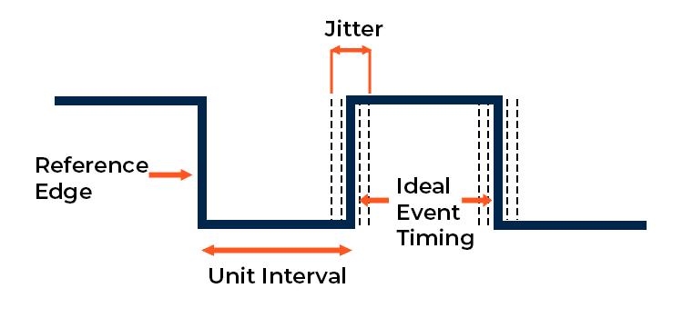
Yes. Jitter is a broad term. “Phase jitter” is the deviation of the signal’s rising and falling edges from their ideal, perfect timing. Other types include “random jitter” (caused by unpredictable noise sources) and “deterministic jitter” (predictable and pattern related). All types of jitter contribute to a higher bit error rate, but phase jitter is a critical metric for high-speed communication systems and a key performance indicator for oscillators.
Jitter is typically measured in picoseconds (ps) or femtoseconds (fs). The blog focuses on phase jitter, but it’s important to also understand other metrics like peak-to-peak jitter and RMS jitter. Peak-to-peak jitter measured the difference between the longest and shortest clock periods in a sample, while RMS (Root Mean Square) jitter is a statistical measure of the standard deviation of the jitter.
Jitter is a system-level issue, not just an oscillator problem. Other components like power supply units (PSUs), which can introduce noise, and even the PCB layout can significantly impact a design’s overall jitter.
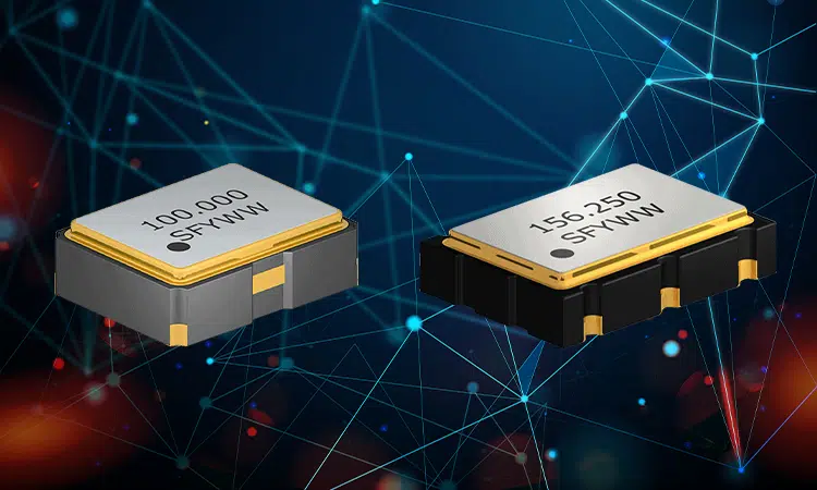
The SUO22L and SUO22P series are designed for a wide range of high-speed applications, including those using optical transceivers. Their low jitter performance makes them ideal for demanding standards like Gigabit Ethernet, Fiber Channel, and high-speed data center interconnects, where signal integrity is paramount. They are not limited to optical applications and are well-suited for any design requiring a precise and stable clock signal.
Yes. Our Board Characterization Services are designed to help you analyze the performance of your final product. We use sophisticated equipment to test for various electrical parameters, including jitter, to ensure your design meets its specifications. This service provides a higher level of confidence in your product’s performance and is a key part of our commitment to being a long-term partner.
Related Content