
Suntsu Chip Antennas offer WiFi, ISM and Mobile communications serving the Smart grid, IOT, Enterprise, Automotive, Telecommunications and Consumer Wireless Industries. We offer a wide range of Frequency bands, including but not limited to, WiFi/ZigBee/Bluetooth band (2400-2500MHz), WiFi Dual band (2400-2500MHz & 4900-5900MHz), ISM bands (433MHz, 863-870MHz & 902-928MHz), GPS Bands (1575.42MHz & 1560-1606MHz) and 3G/GSM/LTE full band (824-960MHz, 1710-2170MHz, 2300-2400MHz & 2490-2690MHz). With package sizes from 1.6×0.8mm up to 40.4×10.8mm. Pick out a standard part number from the data sheets listed below or contact us to request any custom parameters or physical modifications that you may desire and we will design to your specific needs.
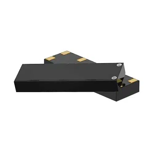
Chip Antennas
| Suntsu Part Number | Images | Package (mm) | Frequency Band (MHz) | Type | Application | Datasheet |
|---|---|---|---|---|---|---|
| SATCA-1GID-WFB1 |  | 1.6 x 0.8 x 0.3 | 2400-2500 | WiFi | WiFi/ZigBee/Bluetooth | |
| SATCA-3C1G1G-WFB1 |  | 3.2 x 1.6 x 1.6 | 2400-2500 | WiFi | WiFi/ZigBee/Bluetooth | |
| SATCA-3C1G1D-WFB1 |  | 3.2 x 1.6 x 1.3 | 2400-2500 | WiFi | WiFi/ZigBee/Bluetooth | |
| SATCA-3C1GF-WFB1 | 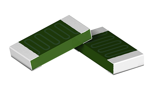 | 3.2 x 1.6 x 0.5 | 2400-2500 | WiFi | WiFi/ZigBee/Bluetooth | |
| SATCA-5A1A1D-WFB1 | 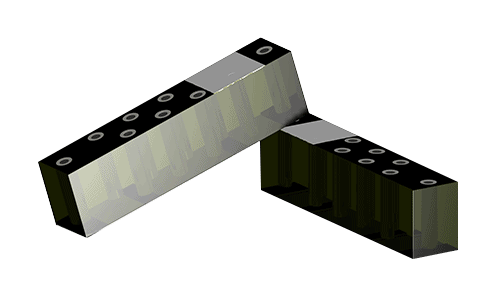 | 5.0 x 1.0 x 1.3 | 2400-2500 | WiFi | WiFi/ZigBee/Bluetooth | |
| SATCA-5A2C1A-WFB1 | 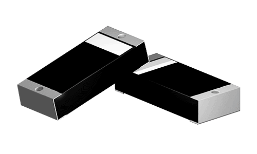 | 5.0 x 2.2 x 1.0 | 2400-2500 | WiFi | WiFi/ZigBee/Bluetooth | |
| SATCA-5A2C1G-WFB1 | 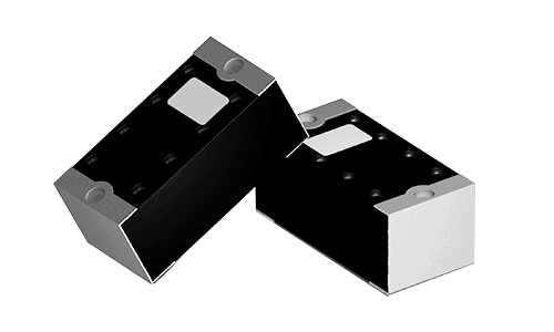 | 5.0 x 2.2 x 1.6 | 2400-2500 | WiFi | WiFi/ZigBee/Bluetooth | |
| SATCA-7A2A2A-WFB1 | 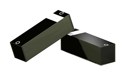 | 7.0 x 2.0 x 2.0 | 2400-2500 | WiFi | WiFi/ZigBee/Bluetooth | |
| SATCA-8A1A1D-WFB1 | 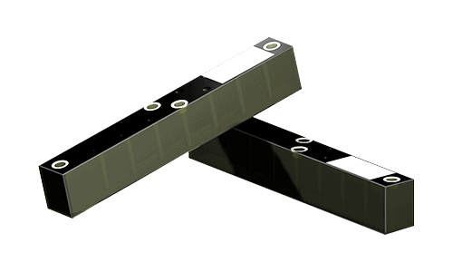 | 8.0 x 1.0 x 1.3 | 2400-2500 | WiFi | WiFi/ZigBee/Bluetooth | |
| SATCA-3C1G1G-WFB3 | 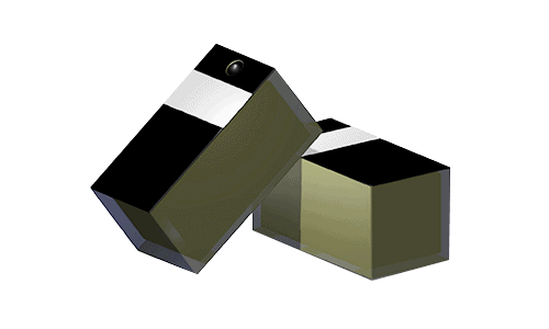 | 3.2 x 1.6 x 1.6 | 2400-2500 & 5150-5850 | WiFi | WiFi Dual band | |
| SATCA-3C1GF-WFB3 | 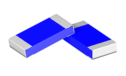 | 3.2 x 1.6 x 0.5 | 2400-2500 & 5150-5850 | WiFi | WiFi Dual band | |
| SATCA-3C1GF-WFB5 |  | 3.2 x 1.6 x 0.5 | 5150-5900 | WiFi | WiFi 5GHz | |
| SATCA-2A1CG-WFB7 |  | 2.0 x 1.2 x 0.6 | 2400-2484 | WiFi | WiFi/ZigBee/Bluetooth | |
| SATCA-3C1GF-WFB8 |  | 3.2 x 1.6 x 05 | 2400-2500 | WiFi | WiFi/ZigBee/Bluetooth | |
| SATCA-10A3C2A-GPB1 |  | 10.0 x 3.2 x 2.0 | 1560-1606 | GPS | GNSS(GPS, GLONASS, BEIDOU, GALILEO) | |
| SATCA-10A3C3J-GPB4 | 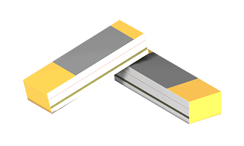 | 10.0 x 3.2 x 3.9 | 1575.42 | GPS | GNSS(GPS, GLONASS, BEIDOU, GALILEO) | |
| SATCA-3C1GF-GPB1 |  | 3.2 x 1.6 x 0.5 | 1560-1606 | GPS | GNSS(GPS, GLONASS, BEIDOU, GALILEO) | |
| SATCA-3C1GF-GPB5 |  | 3.2 x 1.6 x 0.5 | 1575.42 & 2400-2500 | GPS | GNSS(GPS/GLONASS/BDS) + WiFi (2.4GHz)/Bluetooth | |
| SATCA-3C1GF-GPB6 |  | 3.2 x 1.6 x 0.5 | 1575.42, 2400-2500& 5150-5850 | GPS | GNSS + WiFi Dual band | |
| SATCA-16A5BI-ISB2 |  | 16.0 x 5.1 x 0.8 | 433.05-437.79 | ISM | ISM 433MHz | |
| SATCA-12A5A1G-ISB2 |  | 12.0 x 5.0 x 1.6 | 433.05-437.79 | ISM | ISM 433MHz | |
| SATCA-20A5A1G-ISB3 |  | 20.0 x 5.0 x 1.6 | 433.05-437.79 | ISM | ISM 433/450/470 | |
| SATCA-5A3AF-ISB5 |  | 5.0 x 3.0 x 0.5 | 863-870 | ISM | ISM 868MHz | |
| SATCA-12A4A1G-ISB5 |  | 12.0 x 4.1 x 1.0 | 863-870 | ISM | ISM 868MHz | |
| SATCA-5A3AF-ISB7 |  | 5.0 x 3.0 x 0.5 | 902-928 | ISM | ISM 915MHz | |
| SATCA-12A4A1G-ISB7 |  | 12.0 x 4.0 x 1.6 | 902-928 | ISM | ISM 915MHz | |
| SATCA-7A2A2A-ISB6 |  | 7.0 x 2.0 x 2.0 | 863-870 & 902-928 | ISM | ISM 868/915MHz | |
| SATCA-9A4A2A-ISB4 |  | 9.0 x 4.0 x 2.0 | 433.05-437.79, 863-870& 902-928 | ISM | ISM 433/868/915MHz | |
| SATCA-10F3A1G-ISB4 |  | 10.5 x 3.0 x 1.6 | 433.05-437.79, 863-870& 902-928 | ISM | ISM 433/868/915MHz | |
| SATCA-26C7I53C-CEB4 | 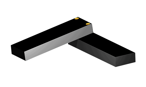 | 26.2 x 7.85 x 3.2 | 824-960 & 1710-2170 | 3G/GSM/LTE | 3G/GSM | |
| SATCA-27A8A3C-CEB4 | 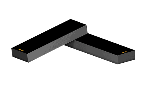 | 27.0 x 8.0 x 3.2 | 824-960 & 1710-2170 | 3G/GSM/LTE | 3G/GSM | |
| SATCA-26A7G53C-CEB4 | 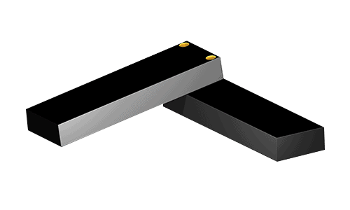 | 26.0 x 7.65 x 3.2 | 824-960 & 1710-2170 | 3G/GSM/LTE | 3G/GSM | |
| SATCA-40E10I3C-CEB4 | 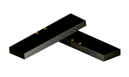 | 40.4 x 10.8 x 3.2 | 824-960 & 1710-2170 | 3G/GSM/LTE | 3G/GSM | |
| SATCA-40I10II-CEB4 |  | 40.8 x 10.8 x 0.8 | 824-960 & 1710-2170 | 3G/GSM/LTE | 3G/GSM | |
| SATCA-35A5A4A-CEB3 |  | 35.0 x 5.0 x 4.0 | 698-798, 824-960, 1710-2170, 2300-2400& 2490-2690 | 3G/GSM/LTE | LTE Full band | |
| SATCA-40A5A6A-CEB3 |  | 40.0 x 5.0 x 6.0 | 698-798, 824-960, 1710-2170, 2300-2400& 2490-2690 | 3G/GSM/LTE | LTE Full band | |
| SATCA-3C1GF-DEB1 |  | 3.2 x 1.6 x 0.5 | 1880-1930 | DECT | DECT | |
| SATCA-6A5AF-UWB1 | 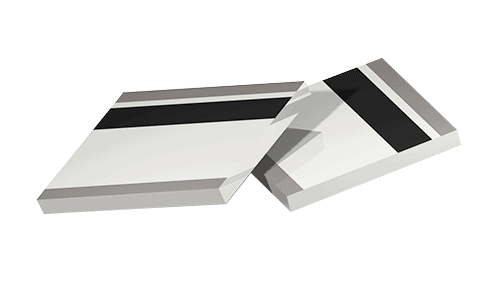 | 6.0 x 5.0 x 0.5 | 6000-8000 | UWB | Ultra-Wide Band |
What is a chip antenna?
A chip antenna is an antenna with a small footprint that you can integrate into a circuit board. The chip antenna receives and radiates high-frequency electromagnetic (EM) waves. Antennas are essential for wireless communication between device and device. The antenna converts EM waves into electric current and vice versa, enabling the transfer of information between two devices.
How does a chip antenna work?
Chip antennas work like any other antenna – it is just a lot smaller in scale. The chip antenna is installed with another electronic circuit that receives and transmits EM or radio waves.
An antenna is a combination of input (receiver) and output (transmitter) transducers. The radio waves received by the input transducer convert to AC electric current. The output transducer takes the AC and converts it to radio waves or whatever frequency of EM waves the chip antenna design accommodates.
A chip antenna, otherwise known as a dielectric resonance antenna, is a cavity resonator. A sintered ceramic fills the cavity, but this does not affect the standing EM wave’s oscillation because the ceramic chosen has high permittivity. The radiation pattern is like a classic dipole antenna but in a much smaller space and with fewer losses.
What is the difference between PCB Antennas and Chip Antennas?
The significant difference between PCB antennas and Chip antennas is the size of the components and the amount of space necessary for them to operate. Modern applications require devices that communicate effectively on multiple wireless frequencies, which means you need an array of antennas. Plus, the available space or the circuit is limited.
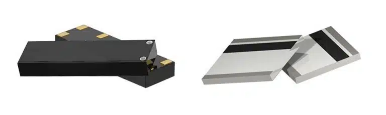
Chip Antennas
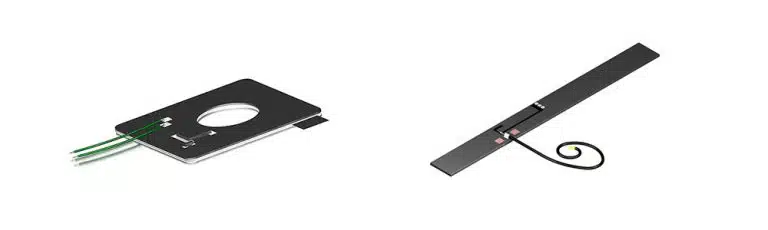
PCB Antenna
In these applications, chip antennas are the best solution because they can sit alongside each other in a small volume. A PCB antenna is larger and requires clear space around it to avoid detuning and interference.
Where can a chip antenna be used? (Applications)
Chip antennas make it possible to hook an object up to a communication network, and you find them everywhere:
- Smart grid – controlling energy supply and use, saving you money on your utilities.
- Internet of things (IoT) – your fridge can tell you when it runs out of milk.
- Tracking – tag objects and people. You always know where to find them.
- Communications – PCs, phones, and anything else that uses WiFi.
- Health – transmit medical details to your doctor from a wearable device.
- Fitness – track your fitness goals and map your daily run.
- Monitoring – transmitting data about industrial processes like fluid flow down a pipe.
A chip antenna lets one thing communicate with another thing, and more innovative uses arrive every day, from a smart key that starts your car to a blood sugar monitor that tells you when to take your insulin.
What Industries Use Chip Antennas?
Any industry can and does take advantage of the opportunities for working smarter and more efficiently with chip antennas:
- Consumer electronics – smartphones, wearables, tablets, gaming machines
- Automotive – automatic diagnostic and software upgrades and keyless operation.
- IT and Communications – anything that talks wirelessly needs an antenna.
- Healthcare – collecting and transmitting health data plus remote monitoring.
- Defense – tracking people and objects for security and other applications.
- Others – marketing, stock control, and data collection and workflow.
What type of frequency bands do we offer?
GPS Chip Antenna: A GPS chip antenna receives and translates signals from the range of Global Positioning Satellites, typically allowing your phone or car software to show you your position on a digital map. The same technology is useful in tracking a fleet of vehicles and other logistical applications. Our GPS chip antenna works with 1575.42MHz.
GNSS Chip Antenna: A GNSS chip antenna operates on the GNSS (Global Navigation Satellite System) satellite frequencies. GPS is part of the GNSS network, first developed for the military and then offered to the civilian population. All GNSS chip antenna can access GPS signals, but the GPS network is more restricted. The GNSS network is perfect for precision agriculture, remote control of machines, transport, and any other application with a geographical component.
Our stock GNSS chip antenna covers GPS (1575.42MHz) and GLONASS, BEIDOU, and GALILEO networks (1560-1606MHz). We can custom design to any other frequency parameters.
ISM Chip Antenna: ISM chip antenna covers the radio frequency bands set aside for Industrial, Scientific, and Medical use: 433MHz, 863-870MHz, and 902-928MHz.
Bluetooth Chip Antenna: Bluetooth chip antenna, WiFi chip antenna, and Zigbee chip antenna all operate in the desirable 2.4-2.5GHz range where most homes and businesses use their network of connected devices.
LTE Chip antenna: LTE Chip antenna covers the cellular frequencies (680-960MHz, 1710-2170MHz, 2300-2400MHz, and 2490-2690MHz). LTE or Long-term Evolution is one of the more common 4G (fourth generation) standards and enables faster data sharing of larger files. A full-band chip antenna covers all the communication protocols up to 4G.
Considering other frequency of chip antennas, we have:
- WiMAX/ Wi-Fi Dual Band: 2400-2500MHz & 4900-5900MHz
- UWB: 3.1 GHz—10.6 GHz
- GSM: 380—1900 MHz
- CDMA: 1850—1995 MHz
It is worth having a chat with one of our experts about your application because we can give you plenty of advice about what the various frequency bands mean for your application. Plus, we can design the chip antenna to match your specific needs.
Aspects that affect the performance of a chip antenna.
The efficiency of a chip antenna depends on the following factors:
- Layout – how the chip antenna rests on the ground plane affects the formation of the resonant circuit necessary for performance.
- Orientation – a single chip antenna needs to be vertical to position the null zones above and below it, allowing omnidirectional performance.
- Impedance matching promotes higher transmission efficiency by minimizing energy loss and reflection and defining the antenna aperture.
- Enclosures – the material chosen for the protective enclosure interacts with and may impact a chip antenna performance.
Other Things to consider when selecting a chip antenna.
The specification features defining your chip antenna are:
- Wireless Network – Choose which wireless network has to be connected with devices. WiFi, GPS, LoRa, LTE, ISM etc.
- Center frequency – the frequency at which you get the best signal strength in the band covering the upper and lower cut-off.
- Bandwidth – this tells you the range of frequencies the antenna will receive and transmit radio signals.
- Gain – a measure (in decibels) of the amount of electromagnetic wave energy directed towards a target in the circuit.
- Impedance – the ratio of voltage to current and impacts on energy efficiency and transmission within the antenna.
- Power rating – relates to the antenna’s ability to transmit radio frequencies into electrical current for efficient operation.
Before you search the chip antenna market for your application, it is worth understanding the specification necessary to achieve your aims. Sometimes, it is better to have chip antennas designed to order rather than compromise with a standard stock item that doesn’t fit your needs.
Advantages and disadvantages of a ceramic chip antenna.
A ceramic chip antenna’s significant advantages are a small size and high quality, allowing them to fit inside smaller devices than a standard antenna.
The advantages of chip antennas include:
- Small size – ideal for wearable devices, and it occupies minimal space on a PCB.
- Reduces the need for a prototype because it has consistent performance.
- Flexible – it sits in multiple configurations and accommodates design changes on the PCB.
- Easy to tune and easy to replace as a component in a design as it is surface mounted.
- Ceramic antennas GPS are less sensitive to other noisy components or environments.
The twin disadvantages of a ceramic chip antenna are that:
- They cost a bit more, but they contribute to a more cost-effective total design, especially in multilayered PCBs.
- They perform slightly less well than the equivalent PCB antenna that is drawn directly onto the circuit board.
Frequently Asked Questions
Why is a chip antenna ceramic?
The precise process of manufacturing a sintered ceramic antenna is a closely guarded commercial secret. Instead of printed metal or some other material, ceramic allows creating an antenna that works as effectively as a larger antenna on a smaller component. The space-saving and the ease of surface mounting the robust chip on your PCB make ceramic the ideal material for producing affordable and efficient chip antennas.
What are the electronics standards for chip antennae?
Chip antennae comply with IEEE 802.11 of the Institute of Electrical and Electronics Engineers (IEEE). These cover protocols for wireless networking and specifies the frequency and channels most useful for these types of components and devices.
What About the Enclosure?
An enclosure of plastic, polymer, or rubber forms the device's outer casing containing the PCB and chip antenna to protect the component from mechanical damage, dust, moisture, and other environmental hazards. A radome is an enclosure that protects the chip antenna. This material mustn't distort the electromagnetic radiation reaching and leaving the antenna.
How to know which frequency band you need?
Frequency is a limited resource with increasing demand as we move into an age of smart devices for everything and everyone. The frequency band depends on your application and what wireless network you need for communication. Each chip antenna specification details the power rating and operating frequency. If you need to track people or objects on a map, you need access to the GNSS network and a GNSS chip antenna. If your devices are in the same room, your application will work better with a WiFi chip antenna, but it all depends on what you need to achieve and the best communication method for that application.
Why Does Antenna Layout Matter?
Printed circuit boards (PCB) connect all the electronic components to make a device function as planned. Today's PCBs may use one to twenty layers and the chip antenna's position on the board matters for performance. A chip antenna works in partnership with the ground plane. The ground plane is an area of copper foil on the PCB that acts as a path for electric current. A ground plane acts as a dipole antenna at a smaller size (3-4cm long by 1-2cm wide) and as a monopole antenna at a larger size. You position the chip antenna at the edge of the PCB in an area without ground and metal components to avoid distortion of electromagnetic radiation transmitted or received by the antenna. Careful attention and design include the proportion and positioning of the microstrip line, feed line, and vias to avoid setting up parasitic resonance circuits and generating unwanted electrical fields at the edge of the PCB.
How Do You Implement a Chip Antenna Properly?
Fractal geometry allows the creation of a small-scale antenna that performs superbly without additional components. A fractal is the same shape regardless of the size – complex, simple, beautiful, and hyper-useful. The head of Romanesco broccoli demonstrates a natural fractal geometry that maximizes exposure to sunlight. Fractal geometry in chip antenna allows creating a tiny antenna that fits into small electronic circuits with a performance that equals or betters a larger antenna. The antenna length is inversely proportional to the desired wavelength of the frequency signal. The ratio can be as small as one-tenth or, more commonly, one-quarter. A chip antenna's radiation pattern is like a bar magnet, and frequencies radiate at right angles to the antenna's long length. This property can give null points at the antenna's ends – a dead zone or blank point. Using two antennas at angles (between 45 and 90 degrees) in the chip gives a more radial emission and works to eliminate the null points. The external enclosure and internal radomes are parts of the design process that can assist, hinder, or be invisible to the chip antenna's operation.