
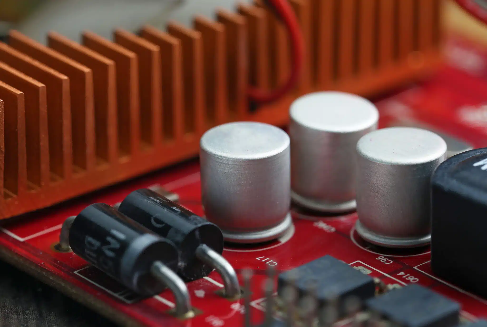
Need Capacitors Fast?
With MLCC and tantalum lead times stretching in 2026, finding available stock matters. Explore Suntsu’s capacitor catalog to find parts that keep your project on schedule.
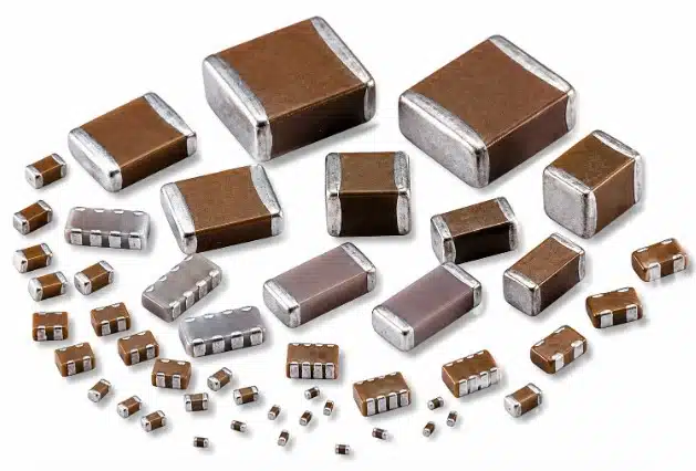
What Is a Ceramic (MLCC) Capacitor?
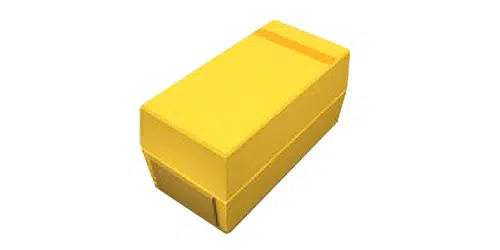
What Is a Tantalum Capacitor?
Manganese Dioxide (MnO2) vs. Polymer Tantalum
Traditional MnO2 tantalum capacitors offer robust performance and widespread availability but exhibit higher equivalent series resistance and can be prone to ignition under extreme thermal or electrical overload conditions. Modern polymer tantalum capacitors substitute the manganese dioxide with a conductive polymer, drastically reducing equivalent series resistance and improving failure safety by mitigating ignition risks during breakdown. Removing MnO2 removes the oxygen source that can fuel ignition when a capacitor shorts in a high-fault-current circuit[2].
Polarity and Reverse Voltage
Unlike ceramic capacitors, tantalum capacitors are polarized devices. Tantalum capacitors must never see continuous reverse voltage. Manufacturers allow only a small transient reverse voltage, commonly 10% of rated voltage (1 V max) at 25 °C, falling to 1% (0.1 V max) at 125 °C[3]. Beyond that, the dielectric degrades and the part can fail short. A polarized capacitor installed backwards is a common cause of failure, so designers should check schematic polarity marks against the physical cathode band during layout and assembly.
MLCC vs. Tantalum Capacitors: Side-by-Side Comparison
Parameter MLCC (Multilayer Ceramic) Tantalum Capacitor Polarity Non-polarized Polarized (Anode/Cathode) Typical Capacitance Range 0.1 pF to ~330 μF (nominal; the highest values are only available at low voltage ratings)[4] 0.1 μF to 1000+ μF[7] ESR / ESL Very low ESR and ESL Higher ESR than MLCC (lower in polymer types) DC Bias Effect Significant drop for Class 2 dielectrics None; capacitance remains stable under bias[5] Temperature Stability None; capacitance remains stable under bias[5] Moderate, predictable shift (typically about −10% at −55 °C to +10–12% at +125 °C)[7] Aging Class 2 exhibits logarithmic aging over time[8] Minimal aging effects Failure Mode Low insulation resistance or short, most often from board-flex cracking[9] Short from dielectric breakdown; MnO2 types can ignite under high fault current, while polymer types greatly reduce ignition risk[2] Voltage Derating Practice Choose the voltage rating from the DC-bias curve so enough effective capacitance remains Required: about 50% for MnO2; 10% (≤10 V rated) or 20% (>10 V rated) for polymer[10] Size / Profile Smallest packages available (01005 and below up to 2220+); low profile in small values Molded chips from 0402 to 7360; low-profile (≤1 mm) high-capacitance options available[1][5][7] Microphonics / Piezoelectric Class 2 dielectrics can produce audible noise; Class 1 (C0G) does not[11][12]. None Relative Cost Low unit cost for commodity values Higher unit cost due to raw material and processing[1]
Note: These differences are why many designs combine both technologies on the same power rail, using MLCCs for high-frequency decoupling and tantalum for bulk storage.
Performance Differences That Matter in Design

While a Class 2 ceramic capacitor may boast a nominal rating of 10 μF on paper, applying DC bias across its terminals can reduce its effective capacitance by 50% to 80%, depending on case size, dielectric, and how close the operating voltage is to the rating. Smaller case sizes are hit hardest[13]. Applying MLCC voltage derating, which means choosing a rated voltage well above the operating voltage, helps preserve effective capacitance. Tantalum capacitors do not suffer from voltage-dependent capacitance loss, making them reliable choices for maintaining steady holdup and bulk storage values under active operating voltages[5].
Equivalent series resistance and inductance dictate how cleanly a capacitor handles high-frequency noise and transient load spikes. MLCCs provide superior filtering in high-frequency applications because their ultra-low equivalent series resistance and inductance minimize voltage ripple[14]. Tantalum capacitors handle moderate ripple currents effectively, but their higher equivalent series resistance generates more internal heat during heavy AC loading.
Class 1 ceramic dielectrics maintain near-zero capacitance variation across temperature swings, whereas Class 2 formulations shift significantly within their specified temperature range[6]. Class 2 ceramics also lose capacitance logarithmically over time, typically about 1–5% per decade-hour. Heating above the Curie point, which happens during reflow, restores the capacitance and restarts the aging clock[8]. Tantalum capacitors don’t age this way. Their capacitance does vary moderately with temperature, typically around −10% at −55 °C to +10–12% at 125 °C, which is far tighter than most Class 2 ceramics under combined temperature and bias stress[7].
Reliability and Failure Modes
Tantalum Short-Circuit Failure and Voltage Derating
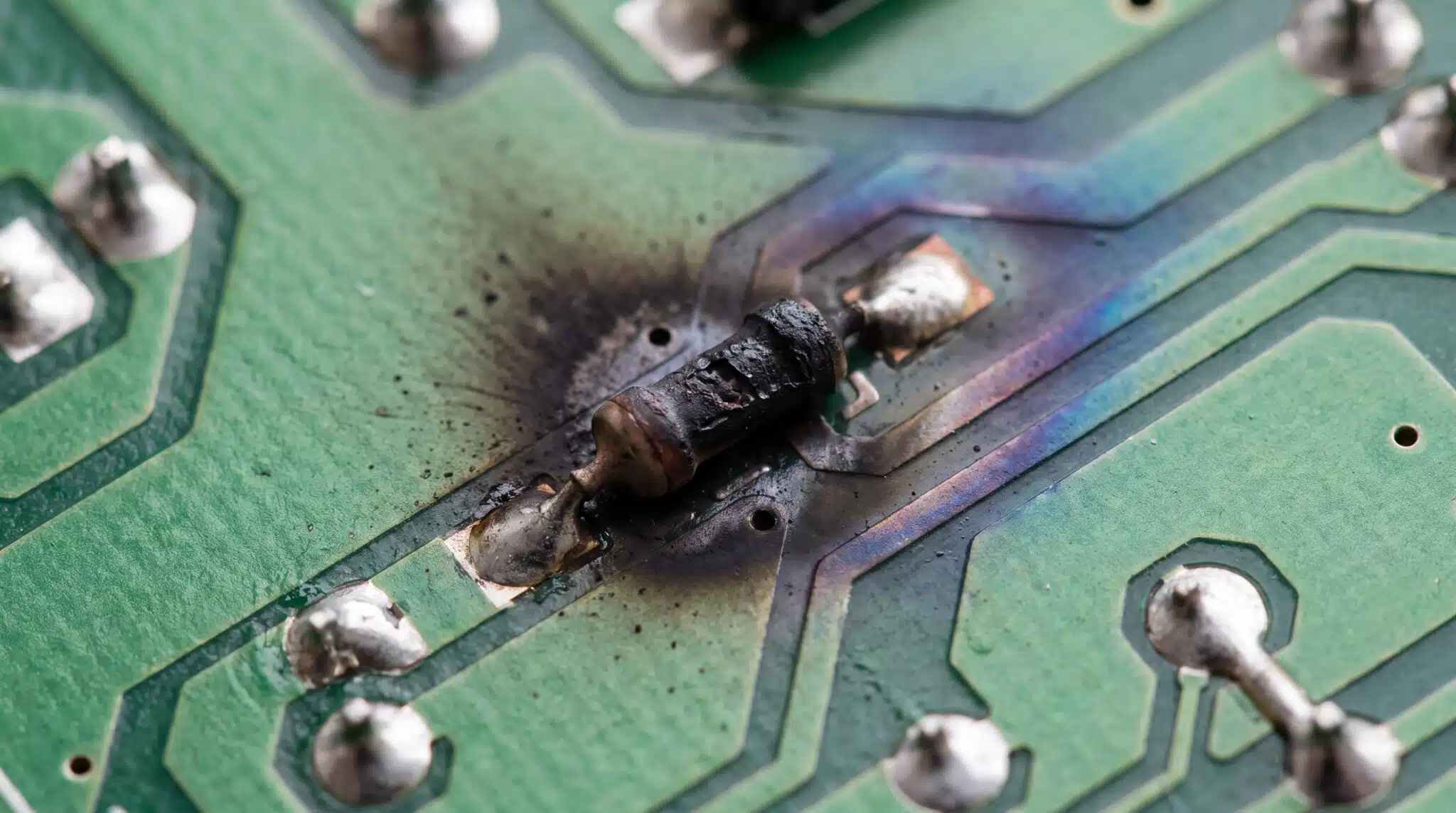
Tantalum capacitors can fail via low-impedance short circuits that draw high fault currents if the dielectric breaks down. To prevent field failures, industry guidelines call for about 50% voltage derating on MnO2 tantalums, especially in low-impedance or high-surge circuits[10][15]. Polymer tantalums need much less: typically 10% for parts rated 10 V or below, and 20% above 10 V[10]. A circuit analysis before prototyping helps identify voltage stress points, including surge current and inrush conditions that can push a tantalum past its derated limit.
MLCC Cracking and Short-Circuit Failure
Cost, Size, and Supply Considerations
Price per Microfarad
When evaluating procurement budgets, ceramic capacitors are usually the lowest-cost option for small- and mid-range capacitance values in low-voltage, high-frequency filtering, although MLCC prices and lead times have been rising. At larger values and case sizes such as 1206, the cost gap with tantalum narrows considerably[1]. Tantalum capacitors generally command a higher unit cost driven by specialized powder processing, manufacturing complexity, and raw material expenses.
Conflict Minerals and Supply Chain Compliance

Current Availability (as of October 2026)
Both technologies are under significant supply pressure in 2026, and the main driver is AI infrastructure buildout more than automotive. High-capacitance and high-voltage MLCCs are now quoted at around 15–20 weeks, and some Samsung Electro-Mechanics high-capacitance parts have reached roughly 40 weeks[20]. Tantalum is tighter still: ingot prices have nearly tripled since the end of 2025, and some EV makers report tantalum capacitor lead times of over a year[21]. Standard-case MLCCs remain comparatively stable at 14–18 weeks[20]. Maintaining visibility into allocation trends, and having a shortage mitigation plan in place before parts go on allocation, is essential for preventing line-down events.
Can You Replace a Tantalum Capacitor with an MLCC?
When a Direct Swap Works
Directly replacing a tantalum capacitor with an MLCC is feasible in high-frequency decoupling locations where lower ESR improves power integrity and where the operating DC voltage stays well below levels that trigger severe capacitance collapse.
Watch-Outs: DC Bias Loss, Regulator Stability (Minimum ESR), Hot-Plug Voltage Spikes, Paralleling Multiple MLCCs
Swapping out tantalums blindly can destabilize power management integrated circuits. Many older linear regulators and some DC-DC converters were designed around the ESR of tantalum or aluminum electrolytic used as output capacitors and need that ESR for loop stability[22]. Dropping in ultra-low-ESR MLCCs can cause oscillation unless you add a small series resistor or confirm the regulator is ceramic-stable, as many modern LDOs are[22][23]. Hot-plugging is the other risk: a low-loss ceramic input capacitor combined with cable inductance forms an underdamped circuit that can cause overvoltage transients by ringing to roughly twice the input voltage[24]. When paralleling multiple MLCCs to match bulk capacitance, ensure layout parasitics do not create unintended resonance peaks[5].
Why Replacement Needs an Engineering Review
Replacing polarized bulk capacitors with ceramic arrays requires rigorous verification of transient response, loop stability margins, and worst-case DC bias derating curves. Because these swaps are usually driven by cost or availability, they belong in a broader BOM analysis rather than a part-by-part substitution.
Decision Framework: When to Choose Ceramic vs. Tantalum
Choose an MLCC When:
- Your circuit requires high-frequency decoupling right at IC power pins.
- Board footprint is tight and the required capacitance at operating voltage is modest.
- Operating voltages are low and predictable, or Class 1 C0G stability is utilized.
- Cost minimization across high-volume production runs is the primary metric.
Choose a Tantalum Capacitor When:
- Stable bulk capacitance is mandatory under active DC bias voltages.
- You need high effective capacitance at the operating voltage within a compact footprint.
- The regulator’s datasheet specifies a minimum output-capacitor ESR (common in older LDO designs).
- Long-term capacitance stability over the product lifespan without aging decay is required.
Secure Your Passive Component Supply Today
Navigating capacitor shortages, DC bias trade-offs, and BOM cost optimizations shouldn’t slow down your product launch. Whether you need hard-to-find tantalum stock or engineering support for an MLCC redesign, Suntsu provides the global sourcing network and technical expertise to keep your electronics production lines moving.
Struggling to find tantalum stock or weighing an MLCC redesign? Suntsu’s sourcing team and engineering specialists can help you find the right capacitor at the right price.
FAQs
Often, yes, especially in high-frequency decoupling spots where an MLCC’s lower ESR can improve performance[1][5]. Before swapping, check the MLCC’s effective capacitance at your operating voltage, since Class 2 ceramics can lose much of their rated value under DC bias[13]. Also confirm that your regulator is stable with low-ESR ceramic capacitors[22][23] and that hot-plug input circuits won’t ring into overvoltage[24].
Neither is more reliable in every case, because they fail in different ways. Tantalum capacitors can fail short if the dielectric breaks down, so they need voltage derating: about 50% for MnO2 types and 10–20% for polymer types[10][15]. MLCCs most often fail from cracks caused by board flexing or thermal shock, which can lead to low insulation resistance or a short[9][16]. Proper derating, layout, and board handling make either type dependable.
Generally, yes. Tantalum capacitors cost more per part because of raw material costs and specialized powder processing, while ceramic capacitors are usually cheapest at small and mid-range values[1]. The gap narrows at larger values and case sizes[1]. In 2026, both types have seen price and lead-time increases, with tantalum under the most pressure[20][21].
A tantalum capacitor’s dielectric is a thin layer of tantalum pentoxide grown on the tantalum anode, and it only blocks current in one direction. If voltage is applied in reverse beyond a small transient limit (commonly 10% of rated voltage at 25 °C, falling to 1% at 125 °C), the dielectric degrades and the part can fail short[3]. That’s why tantalum capacitors must always be installed with the correct orientation.
Related Content
References
- EPCI (European Passive Components Institute). “MLCC Capacitors Availability First Aid – Tantalum/NbO to MLCC Replacement Guidelines” Available at: https://passive-components.eu/mlcc-capacitors-availability-first-aid-tantalum-nbo-to-mlcc-capacitors-replacement-guidelines
- Vishay Sprague. “vPolyTan™ Polymer Tantalum Capacitors” Available at: https://www.vishay.com/docs/40284/vpolytanpolymertantalumcapacitors.pdf
- KYOCERA AVX. “Reverse Voltage Behavior of Solid Tantalum Capacitors” Available at: https://www.ethertronics.com/docs/techinfo/Reverse_Voltage_Behavior.pdf
- Murata Manufacturing. “Expanded lineup of 1206- and 1210-size MLCCs in the range exceeding 100µF” Available at: https://www.murata.com/news/capacitor/ceramiccapacitor/2015/0511
- KYOCERA AVX. “MLCC & Tantalum Interchangeability” Available at: https://www.ethertronics.com/docs/literature/MLCC-Tantalum-Interchangeability-Brochure.pdf
- TDK. “Temperature characteristics guide (3): Which temperature characteristics are commonly referenced for MLCCs?” Available at: https://product.tdk.com/en/contact/faq/capacitors-0051.html
- KEMET. “‘T491 Series Solid Tantalum Chip Capacitors,’ Datasheet” Available at: https://html.alldatasheet.net/html-pdf/188816/KEMET/T491E154M035AG/1298/8/T491E154M035AG.html
- KEMET. “Ceramic Capacitor Basics: Aging” Available at: https://www.digikey.be/en/ptm/k/kemet/ceramic-capacitor-basics/tutorial?slide=17
- KEMET. “Technical Overview of Flex Mitigation Solutions” Available at: https://www.mouser.com/pdfdocs/TechnicalOverviewofFlexMitigationSolutions.pdf
- KEMET. “Tantalum Capacitor Basics: MnO2 vs. Polymer” Available at: https://www.digikey.com/en/ptm/k/kemet/tantalum-capacitor-basics/tutorial?slide=8
- Texas Instruments. “How to Reduce Acoustic Noise of MLCCs in Power Applications” Available at: https://www.ti.com/lit/pdf/ssztb09
- Monolithic Power Systems. “DC Power Supply Noise Reduction and Measurement” Available at: https://media.monolithicpower.com/mps_cms_document/2/0/2020-aip-dc-power-supply-noise-reduction-and-measurement_r1.0.pdf
- Electronic Design. “Diagnosing Class II MLCC Effective Capacitance and Aging Under DC Bias” Available at: https://www.electronicdesign.com/technologies/analog/article/21135733/diagnosing-class-ii-mlcc-effective-capacitance-and-aging-under-dc-bias
- Avnet/Vishay. “Substitution of Solid Tantalum and Tantalum Polymer Capacitors for Surface-Mount MLCCs” Available at: https://www.avnet.com/americas/resources/article/substitution-of-solid-tantalum-and-tantalum-polymer-capacitors/
- Electronic Design. “Tantalum Polymer Capacitors Achieve Higher Voltage Ratings” Available at: https://www.electronicdesign.com/technologies/components/passives/article/21190537/tantalum-polymer-capacitors-achieve-higher-voltage-ratings
- DigiKey. “Ceramic Capacitor Failure: Design Solutions & Mitigating Board Flex Cracking” Available at: https://forum.digikey.com/t/ceramic-capacitor-failure-design-solutions-mitigating-board-flex-cracking/26195
- Kelley Drye & Warren LLP. “Securities and Exchange Commission (SEC) Approves Final Conflict Mineral Rule” Available at: https://www.kelleydrye.com/viewpoints/client-advisories/securities-and-exchange-commission-sec-approves-final-conflict-mineral-rule
- European Parliament and Council, Regulation. “Regulation (EU) 2017/821 of the European Parliament and of the Council of 17 May 2017” Available at: https://eur-lex.europa.eu/eli/reg/2017/821/oj
- TDK. “TDK’s Guide to Electrically Conductive Adhesives (4): Does TDK offer MLCCs for use with conductive epoxy?” Available at: https://product.tdk.com/en/contact/faq/capacitors-0073.html
- ETNews. “AI Server Demand Pushes MLCC Lead Times Toward 10 Months” Available at: https://en.etnews.com/20260818200005
- TrendForce. “Tantalum Prices Nearly Triple on AI Demand, Supply Disruptions; EV Capacitor Lead Times Reportedly Top 1 Year” Available at: https://www.trendforce.com/news/2026/08/25/insights-tantalum-prices-nearly-triple-on-ai-demand-supply-disruptions-ev-capacitor-lead-times-reportedly-top-1-year/
- Texas Instruments. “ESR, Stability, and the LDO Regulator” Available at: https://www.ti.com/lit/pdf/slva115
- Texas Instruments. “Ceramic Capacitors Replace Tantalum Capacitors in LDOs” Available at: https://www.ti.com/lit/pdf/slva214
- Analog Devices. “Ceramic Input Capacitors Can Cause Overvoltage Transients” Available at: https://www.analog.com/media/en/technical-documentation/application-notes/an88f.pdf