
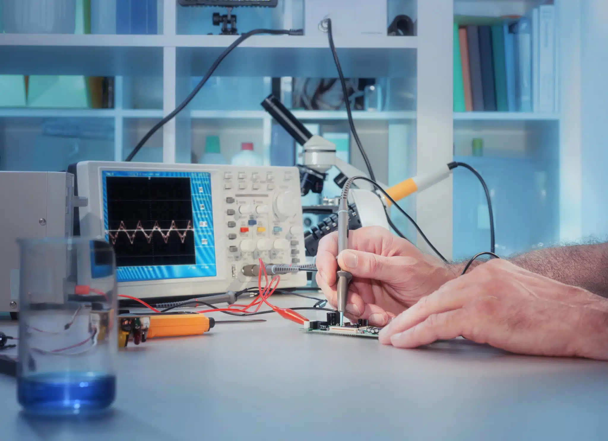
 A power good signal (often labeled PGOOD, PG, or PWRGD on datasheets, and PWR_OK in PC power supplies) is an output from a voltage regulator or power management IC (PMIC) that indicates when its output voltage is within a specified range and is safe to use
Build a More Reliable Power Architecture
From switching regulators to supervisors, Suntsu stocks the power management ICs that keep multi-rail designs sequencing correctly.
What Is a PGOOD (Power Good) Signal?
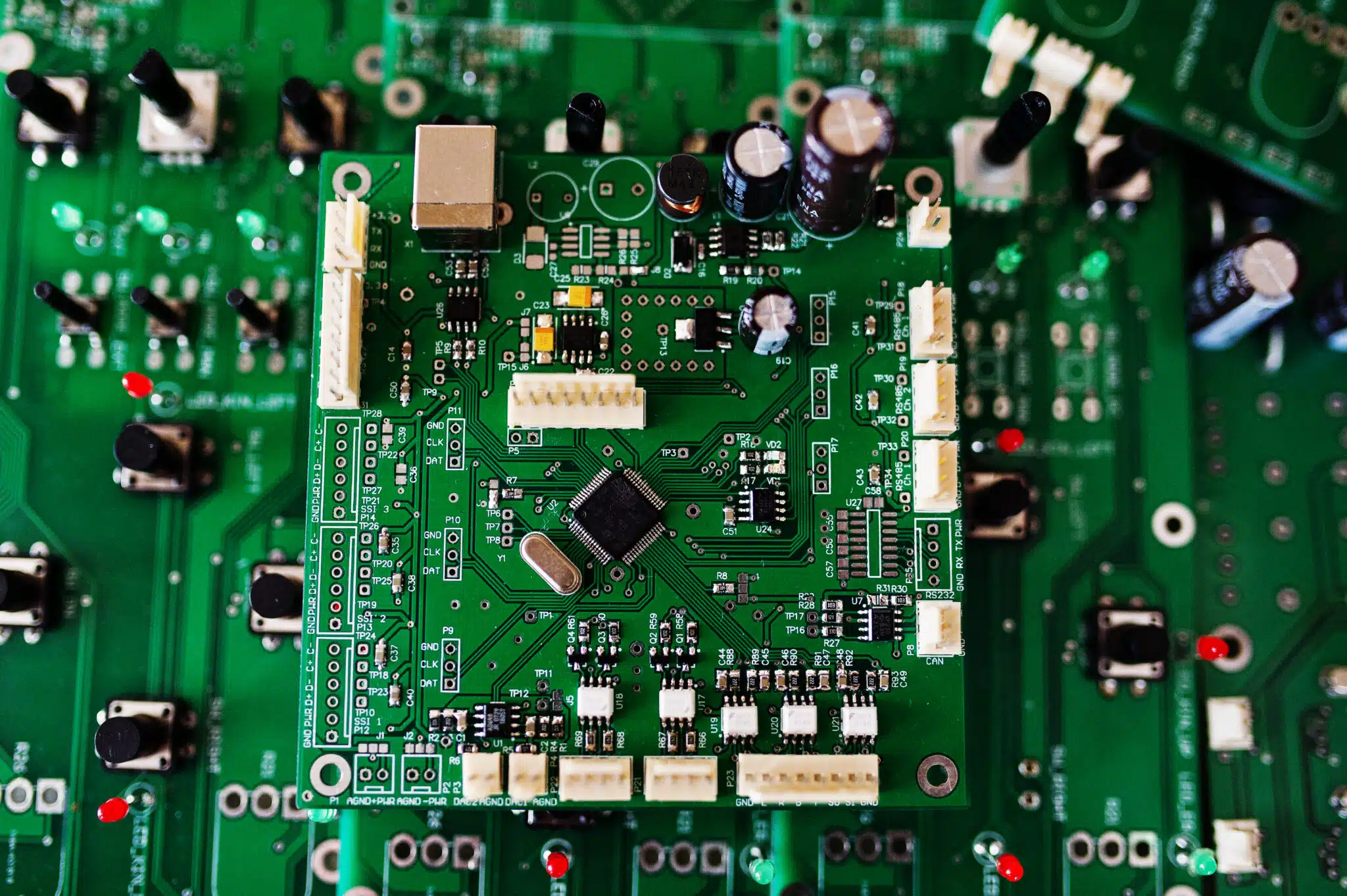 A power good signal is a digital status output found on
How PGOOD Thresholds and Delay Timers Work
PGOOD monitoring depends on high-precision voltage comparator circuits integrated directly within power ICs or external supervisory devices. These circuits continuously compare a feedback or sense voltage (typically the output divided down by a resistor network) against an internal reference[1].

Voltage Threshold Accuracy
The voltage threshold defines the output level at which the comparator toggles the PGOOD line. Many regulators assert PGOOD once the output rises to roughly 90% to 95% of nominal and de-assert it if the rail falls below roughly 88% to 92%. For example, one TI buck converter releases PGOOD when its feedback voltage is between 91% and 106% of the internal reference and pulls it low below 89% or above 108%[1]. Another uses a −6%/+7% good window with −8%/+9% fault thresholds[2]. UTC’s UD052012 synchronous buck converter releases its open-drain PG pin once the output rises above 90% of nominal and actively holds it low during soft-start, standby, and shutdown[13]. Always confirm the exact values in your device’s datasheet. Threshold accuracy also varies. Dedicated window supervisors can hold their thresholds to within about ±1% over temperature[4], which is why high-reliability designs often pair a regulator’s built-in PGOOD with an external supervisor. Many regulators and PMICs also include an upper (overvoltage) threshold, typically around 105% to 110% of nominal, so PGOOD also drops if the rail rises too high[1][2].

Delay/Debounce Timing
Power rails do not reach target operating voltages instantaneously; they exhibit rise times influenced by soft-start settings and load capacitance. To prevent premature execution during voltage ringing or initial overshoot, PGOOD circuits incorporate built-in delay and debounce timers. Once the output voltage crosses the valid threshold, an internal timer holds PGOOD low for a delay period (tDELAY). Regulators with built-in PGOOD often use short, fixed delays. One TI buck converter, for example, waits 272 switching cycles before releasing PGOOD[1]. Standalone supervisors and system-level power supply units may use much longer delays. The Intel ATX power supply design guide, for instance, calls for at least 100 ms between the rails stabilizing and PWR_OK asserting[5]. Dedicated PC power supply supervisors build this kind of delay in. UTC’s 3513, for example, specifies a 300 ms typical delay (200 ms to 490 ms) between its power-good input and its open-drain power-good output[14]. Many devices also filter the falling edge so that brief ripple or transients don’t cause false fault indications[1]. Together, these delays give the rail time to stabilize before downstream components begin to operate.
Parameter Typical Value Range Primary Function in PMIC Design Undervoltage (UV) Threshold 90%-95% of VOUT Asserts PGOOD high when voltage ramps above safe lower bound. Overvoltage (OV) Threshold 105%-112% of VOUT De-asserts PGOOD if voltage exceeds safe operational maximums, Threshold Hysteresis 0.5%-3% of VOUT Prevents PGOOD chatter caused by normal ripple voltage. Power Good Delay (tDELAY) ~10 μs to several hundred ms (device-dependent) Debounces output voltage stabilization prior to signaling ready. Active Output State Typically logic HIGH (high-impedance on open-drain outputs); supervisor RESET outputs are often active-low Indicates power rails are within specified tolerance.
Using PGOOD for Power Sequencing
In systems containing complex processors, high-performance FPGAs, or multi-stage analog circuits, the device datasheet often specifies a required or recommended power-up order[7]. Turning on core, I/O, and memory rails in the wrong order can cause excessive inrush current, forward-bias internal protection diodes, trigger latch-up, or leave I/Os in an undefined state[7][9].
Chaining PGOOD to Enable Pins
The simplest hardware technique for controlling start-up order is event-based power sequencing, achieved by chaining the PGOOD signal of an upstream supply directly to the enable (EN) pin of the next downstream regulator.
- Stage 1 Activation: The primary supply (e.g., a 5.0 V bus regulator) starts up.
- Voltage Verification: The primary regulator output reaches nominal voltage, and its internal timer satisfies tDELAY.
- Trigger Downstream: The primary regulator asserts its PGOOD pin HIGH.
- Stage 2 Activation: Because the PGOOD pin connects directly to the Enable pin of the secondary regulator (e.g., a 1.8 V supply), the secondary rail begins its soft-start ramp.
- System Readiness: The process repeats through subsequent stages in the order specified by the load device’s datasheet. Note that many devices require the core rail first. AMD’s Artix-7 FPGAs, for example, recommend VCCINT, then VCCBRAM, VCCAUX, and finally VCCO[7].
This cascade approach enforces start-up order in hardware without microcontroller timing loops[8]. It has limits, however. A simple PGOOD-to-EN chain doesn’t control power-down order, so designs with strict shutdown requirements typically use a dedicated power sequencing IC[8][9].
Some regulators go a step beyond a simple PGOOD flag. 3PEAK’s TPP20608x family of 17 V, 6 A synchronous buck converters pairs an open-drain power-good output with a soft-start function that can be set by an external resistor or configured for sequencing and tracking mode, giving designers control over both the order and the ramp of each rail[15].
PGOOD for Fault Detection and System Diagnostics
Beyond managing power sequencing, PGOOD lines act as real-time hardware flags that help the system detect abnormal power conditions and faults. If a sudden load transient, thermal event, or short circuit pulls an active voltage rail below the comparator threshold, the PGOOD signal de-asserts after a short deglitch interval. That interval varies widely, from a few switching cycles on some regulators[1] to a couple of milliseconds on others[3], so check the datasheet if your fault response is time-critical. PGOOD also typically drops immediately if the regulator is disabled, falls into undervoltage lockout, or enters thermal shutdown[1].
 Connecting PGOOD lines to system
Wiring PGOOD to MCUs and Supervisory Circuits
Integrating a power good output into a broader digital system requires careful consideration of board-level pin logic and electrical interface characteristics.
Open-Drain vs. Push-Pull PGOOD Outputs
PMICs and discrete regulators deliver PGOOD signals using one of two primary output topologies: open-drain or push-pull. Selecting the correct interface type determines how the signal will connect to host controllers.
- Open-Drain Outputs: An open-drain PGOOD pin uses an internal N-channel MOSFET that connects the output to ground when power is not good, provided the IC has enough bias to drive that MOSFET (see Common PGOOD Design Mistakes, below)[3]. When the power rail reaches specification, the internal MOSFET turns off, leaving the output high-impedance. This topology requires an external pull-up resistor connected to a valid logic supply rail. Open-drain outputs offer significant flexibility, as they allow wired-AND connections where multiple PGOOD pins pull down a single common line. They also enable level-shifting, allowing a regulator running on a 5 V input to drive a 3.3 V or 1.8 V microcontroller input pin safely[10].
- Push-Pull Outputs: Push-pull outputs feature both internal P-channel and N-channel transistors, allowing the driver to actively source current HIGH or sink current LOW. Push-pull pins do not require external pull-up resistors, reducing overall component counts. However, push-pull pins cannot be tied directly together in a multi-rail wired-AND topology, nor can they adapt output logic voltage levels independently.
Supervisor families often offer both topologies, so you can match the output to the receiving logic. 3PEAK’s TPV803, TPV809, and TPV810, for instance, share the same 200 ms typical reset timeout, but the TPV803 uses an open-drain, active-low output that needs a pull-up resistor, while the TPV809 (active-low) and TPV810 (active-high) use push-pull outputs[17].
Feature Open-Drain PGOOD Push-Pull PGOOD External Resistor Required? Yes (Pull-up resistor needed) No (Actively driven HIGH and LOW) Wired-AND configurations Supported (Tie multiple outputs together) Not Supported (Causes bus contention) Logic Level Flexibility High (Pull up to preferred voltage domain) Low (Fixed by internal supply rail) Unpowered Behavior Undefined until the IC has minimum bias; can float to the pull-up voltage if the pull-up rail is powered first[3][11] Undefined below the IC's minimum operating voltage; some devices recommend a pull-down resistor to hold the line low[12] Component Count Requires 1 external resistor per node Zero external components
When connecting an open-drain PGOOD output to an interrupt pin on a host processor, choose the pull-up resistor carefully. Values commonly fall between 10 kΩ and 100 kΩ[1]. Lower values give faster rise times but draw more current whenever PGOOD is low. Also confirm that the pull-up voltage doesn’t exceed the PGOOD pin’s absolute maximum rating[1].
On low-voltage converters, that limit is often tied to the input supply. UTC’s UD052012, for example, rates its PG pin only up to VIN, so the pull-up rail must not exceed the converter’s input voltage[13].
Common PGOOD Design Mistakes
Despite the apparent simplicity of PGOOD status lines, subtle design oversight can cause unreliable hardware behavior. Avoid these common design pitfalls:
1. Choosing the Wrong Pull-Up Voltage
The pull-up rail determines both PGOOD’s logic level and how it behaves before the regulator is biased. Pulling up to the monitored output ties PGOOD’s high level to that rail, which may not match the receiving logic (a 1.0 V core rail can’t produce a valid high for a 3.3 V input). Pulling up to an always-on standby rail gives a clean logic level, but it can generate a brief false “power good” indication before the regulator’s own input supply comes up[3]. Where available, TI recommends a pull-up derived from the regulator itself, such as its internal bias (VREG) pin[3]. If you use an always-on rail, make sure downstream logic ignores PGOOD until the regulator’s input is valid.
2. Ignoring Unpowered Pin States
During power-up, a regulator’s internal control circuits require minimum operational bias before its internal open-drain MOSFET can actively sink current. Prior to reaching this threshold, the PGOOD pin may momentarily float HIGH due to the external pull-up resistor, delivering a false “Power Good” indication. In applications where a false indication would be harmful, choose supervisors whose output is guaranteed valid down to a very low supply voltage, or “glitch-free” supervisors designed to hold the output low even at 0 V[11][12]. 3PEAK’s TPV803/809/810 supervisors, for example, guarantee a valid reset output down to VCC = 1 V[17].
3. Ignoring Noise on the PGOOD Line
Noise on the pull-up rail, or coupling from nearby switch nodes, can cause false transitions on reset lines driven by PGOOD. Decouple the pull-up supply, route PGOOD away from switch nodes and inductors, and if needed add a small filter capacitor at the receiving input. Keep in mind that this capacitance slows the rising edge and adds delay.
4. Paralleling Push-Pull Outputs Directly
Tying multiple push-pull PGOOD pins together directly will drive conflicting logic states, leading to high contention currents, thermal stress, and hardware damage. Always use discrete logic gates or open-drain outputs when combining status signals.
PGOOD-Ready Power Management from UTC and 3PEAK
Suntsu supplies power management ICs from UTC (Unisonic Technologies) and 3PEAK, two manufacturers whose portfolios cover the PGOOD functions discussed above, from regulators with built-in power-good outputs to standalone supervisors.

UTC (Unisonic Technologies)
A Taiwan-based maker of power management and analog ICs, UTC offers compact synchronous buck converters such as the UD052012, whose open-drain PG output stays low through soft-start and shutdown and releases once the output passes 90% of nominal[13]. For system-level supplies, UTC’s PC power supply supervisors, such as the 3513, combine an open-drain power-good output and a built-in 300ms typical delay with over- and undervoltage monitoring of the 3.3 V, 5 V, and 12 V rails[14].

3PEAK
3PEAK’s buck converter lineup includes the TPP20608x (4.5 V to 17 V input, 6 A), with an open-drain power-good output and sequencing/tracking soft-start[15], and the TPP05608 (2.8 V to 6 V input, 6 A), which combines power good with UVLO, current limit, and thermal shutdown and holds output accuracy to better than 1% over temperature for low-voltage loads[16]. For external monitoring, the TPV803/809/810 supervisors draw about 2.2 µA and offer a choice of open-drain or push-pull reset outputs[17].
Pairing a regulator’s built-in PGOOD with a standalone supervisor from either line is a practical way to apply the layered monitoring approach described earlier: the regulator flags its own rail, while the supervisor provides a tighter, independently timed reset for the processor.
Conclusion
 PGOOD may be a simple status signal, but its thresholds, timing, output type, and pull-up choice determine whether your rails sequence reliably or produce intermittent, hard-to-trace faults. Optimizing your power management architecture requires careful component selection and thorough design verification. Whether you need low-noise linear regulators, high-efficiency
Need help selecting or sourcing power management components for your next design? Suntsu’s technical team can support you with component selection, design-in assistance, and samples.
FAQs
It depends on the device, so always check the datasheet. Many regulators assert PGOOD at roughly 90% to 95% of nominal output. For example, the TI TPS54824 releases PGOOD when its feedback voltage is between 91% and 106% of the internal reference, and pulls it low below 89% or above 108%[1]. The TI LMR16030 uses a −6%/+7% good window with −8%/+9% fault thresholds[2].
Open-drain PGOOD outputs need an external pull-up resistor to a valid logic rail, while push-pull outputs drive the line on their own[10]. Values commonly fall between 10 kΩ and 100 kΩ. Lower values give faster rise times but draw more current whenever PGOOD is low. Make sure the pull-up voltage doesn’t exceed the pin’s absolute maximum rating[1].
Connecting one regulator’s PGOOD pin to the next regulator’s enable (EN) pin makes each rail wait until the previous one is in regulation. This enforces start-up order in hardware without microcontroller timing loops[8]. A simple PGOOD-to-EN chain doesn’t control power-down order, though, so designs with strict shutdown requirements typically use a dedicated sequencing IC[8][9].
An open-drain PGOOD pin can only pull low once the regulator has enough internal bias to turn on its output MOSFET. Before that, the pull-up resistor can float the line high, especially if the pull-up rail powers up before the regulator’s input[3][11]. Pulling up to the regulator’s own bias pin where available, or using supervisors designed to hold their output low down to 0 V, avoids this problem[3][11][12].
Related Content
References
- Texas Instruments. “TPS54824 4.5-V to 17-V Input, 8-A Synchronous Step-Down SWIFT Converter datasheet” Available at: https://www.ti.com/document-viewer/TPS54824/datasheet/power-good-x2025
- Texas Instruments. “LMR16030 SIMPLE SWITCHER® 60-V, 3-A Step-Down Converter datasheet” Available at: https://ti.com/document-viewer/LMR16030/datasheet/GUID-3CBA3A56-044C-45CE-B42B-5A68CA25C594
- Texas Instruments. “Good Pin Practices with Buck Converters” Available at: https://www.ti.com/lit/pdf/sszta52
- Texas Instruments. “TPS3702 High-Accuracy Over- and Undervoltage Monitoring datasheet” Available at: https://www.ti.com/product/TPS3702
- Intel Corporation. “ATX Version 3 Multi Rail Desktop Platform Power Supply Design Guide” Available at: https://edc.intel.com/content/www/us/en/design/ipla/software-development-platforms/client/platforms/alder-lake-desktop/atx-version-3-0-multi-rail-desktop-platform-power-supply-design-guide/2.0/2.01/timing-housekeeping-and-control-required/
- PMBus. “PMBus Power System Management Protocol Specification” Available at: https://pmbus.org/wp-content/uploads/2022/01/PMBus-Specification-Rev-1-3-1-Part-II-20150313.pdf
- AMD. “Artix-7 FPGAs Data Sheet: DC and AC Switching Characteristics” Available at: https://docs.amd.com/v/u/en-US/ds181_Artix_7_Data_Sheet
- Texas Instruments. “FPGA Power Made Simple: Sequencing” Available at: https://www.ti.com/lit/pdf/sszt890
- Texas Instruments. “Sequencing Solutions: Simple, Reliable and Cost-Effective” Available at: https://ti.com/lit/pdf/sszt944
- Analog Devices. “Choosing Supervisor Outputs” Available at: https://www.analog.com/en/resources/technical-articles/choosing-supervisor-outputs.html
- Analog Devices. “The ABCs of Glitch-Free Voltage Supervisors” Available at: https://www.analog.com/en/resources/technical-articles/the-abcs-of-glitchfree-voltage-supervisors.html
- Analog Devices. “MAX6443–MAX6452 µP Reset Circuits with Long Manual Reset Setup Period datasheet” Available at: https://www.analog.com/media/en/technical-documentation/data-sheets/max6443-max6452.pdf
- Unisonic Technologies (UTC). “UD052012 Synchronous Buck Converter datasheet” Available at: https://www.unisonic.com.tw/uploadfiles/836/part_no_pdf/UD052012.pdf
- Unisonic Technologies (UTC). “3513 PC Power Supply Supervisor datasheet” Available at: http://www.utc-ic.com/uploadfile/2011/0905/20110905103940400.pdf
- 3PEAK. “TPP20608x 17-V Input, 6-A, Synchronous Step-Down DC-DC Voltage Converter” Available at: https://www.3peak.com/mid-voltage-buck-converters/tpp206080
- 3PEAK. “TPP05608 2.8-V to 6-V Vin, 6-A Synchronous Step-down Regulator” Available at: https://www.3peak.com/low-voltage-buck-converters/tpp056080
- 3PEAK. “TPV803/809/810 Low Voltage Supervisory Circuit datasheet” Available at: https://static.3peak.com/res/doc/ds/Datasheet_TPV803-TPV809-TPV810.pdf