
Need More Headroom?
Higher voltage ratings, larger case sizes, and C0G dielectrics are the fastest ways to protect effective capacitance. Explore our capacitor lineup to find parts that fit your derating targets.
What Is MLCC Voltage Derating?
When selecting components for a printed circuit board, engineers often go strictly by their nominal datasheet values. However, surface-mount components rarely operate in laboratory conditions. MLCC voltage derating addresses the reality that ceramic capacitors change behavior under electrical and thermal stress.
Voltage derating requires applying a DC voltage that is lower than the component’s maximum rated limit. This practice provides a safety margin that reduces the risk of dielectric breakdown, slows long-term wear-out, and accommodates transient voltage spikes and surges[1][2]. Beyond reliability, derating accounts for how electrical fields alter the physical structure of ceramic dielectrics, directly impacting the component’s capability to store charge.
Why DC Bias Causes Capacitance Loss in Class 2 MLCCs
Class 1 vs. Class 2 Behavior Under Bias
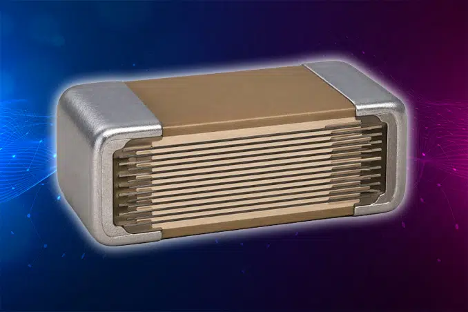
In contrast, Class 1 dielectrics like C0G (NP0) use paraelectric formulations, most commonly calcium zirconate (CaZrO₃)-based ceramics[5][6]. These dielectric materials do not exhibit domain switching under an electric field. Consequently, Class 1 MLCCs maintain a stable capacitance value across their entire applied voltage range, experiencing effectively no capacitance loss due to DC bias[5]. When your design requires strict capacitance stability—such as in filters, oscillators, or timing circuits—specifying Class 1 components eliminates DC bias headaches entirely. In crystal oscillator circuits, any drift in the load capacitance directly degrades frequency stability.
MLCC Derating Factors to Account For
Calculating the actual capacitance available in your circuit requires evaluating four distinct operational factors.

The DC voltage present across the capacitor terminals is usually the predominant contributor to capacitance loss in Class 2 parts. As the DC voltage increases toward the rated limit, usable capacitance can drop sharply; some Class 2 parts lose as much as 90% at rated voltage[5].
Operating temperature shifts capacitance based on the dielectric characteristic code. For example, an X7R dielectric can vary by ±15% across its operating temperature range of −55°C to +125°C, while an X5R operates up to +85°C[3]. High ambient temperatures, common in harsh environments such as outdoor enclosures and densely packed power stages, combined with internal self-heating push capacitors into regions where capacitance drops further.
Class 2 ferroelectric ceramics exhibit logarithmic aging over time. As the crystal structure stabilizes below its Curie point, the capacitance decreases at a predictable rate per decade of hours (typically about 2% to 3% per decade for X7R, while X5R datasheets cite anywhere from about 3% to 7%[7][8]). The aging clock resets whenever the part is heated above its Curie point (roughly 125°C to 130°C), which normally happens during reflow soldering[5][9].
High AC ripple currents, which are heaviest on the input and output capacitors of switching regulators and other DC-DC converters, induce internal power dissipation and self-heating. If the internal temperature exceeds the rated operating limit, the dielectric material degrades faster, shortening component life span. Murata, for example, recommends keeping self-heating below 20°C (measured at 25°C ambient) and keeping the part’s surface temperature within its rated maximum[10]. AC amplitude also shifts the capacitance of Class 2 parts directly, so evaluate parts at your actual ripple voltage[5].
How to Calculate Effective Capacitance
To determine the true performance of your capacitor in an operating circuit, you must calculate its effective capacitance by multiplying the nominal value by each derating factor.
Effective Capacitance = Nominal Capacitance × Bias Factor × Temperature Factor × Aging Factor
Worked Example
Consider an illustrative 10 microfarad, 25V X7R MLCC in an 0805 case size, operating with a 12V DC bias rail at an ambient temperature of +85°C, over a 10-year service life.
- Nominal Capacitance: 10 µF
- Bias Factor: Consulting an illustrative manufacturer datasheet curve for a 12V bias on a 25V-rated part, the capacitance retention is approximately 50% (Factor = 0.50).
- Temperature Factor: An X7R capacitor is specified to stay within ±15% across −55°C to +125°C. Applying that worst-case limit at +85°C is conservative (Factor = 0.85); typical parts drift less, so check the manufacturer’s temperature curve[3].
- Aging Factor: Datasheet capacitance is specified at a referee time after the last heat above the Curie point, often 1,000 hours for X7R[17], so only aging beyond that point reduces the value further. A 10-year life (about 87,600 hours) adds roughly two more decades; at about 2.5% per decade, that is a 5% loss (Factor = 0.95).
Effective Capacitance = 10 µF × 0.50 × 0.85 × 0.95 ≈ 4.04 µF
Even though you specified a 10 µF component on your bill of materials, your circuit receives roughly 4 µF of usable capacitance under these operating conditions. If your decoupling filter requires a minimum bulk capacitance to maintain stability, this capacitance reduction can trigger unexpected ripple or reset issues that often stay hidden until circuit analysis or field testing exposes them. The stakes are highest on regulator outputs, where many LDO regulators specify a minimum effective output capacitance for loop stability.
Voltage Derating Guidelines for Reliability
Commercial and Consumer Designs
For cost-sensitive consumer electronics where board space is tight, designers typically derate MLCC operating voltage to 70% to 80% of the maximum rated voltage (e.g., operating a 12V rail on a 16V part, which is 75% of rating).
Automotive and Industrial Designs
Automotive and industrial applications demand higher field reliability, which is why automotive designs typically specify AEC-Q200 qualified MLCCs. Many automotive and industrial design guidelines limit applied DC voltage to 50% to 60% of the component rating.
High-Reliability, Medical, and Aerospace Designs
Mission-critical systems often mandate strict derating profiles as part of a broader high-reliability design strategy, with capacitors operating at or below 50% to 60% of their rated voltage limit. NASA Goddard’s general derating guideline, for example, caps capacitors at 60% of rated voltage, and some space-program requirements for ceramic capacitors specify 50%[11][12].
Note: Always defer to your customer’s or program’s internal derating standard where one exists.
How Case Size and Voltage Rating Affect Bias Loss
Larger Case Sizes
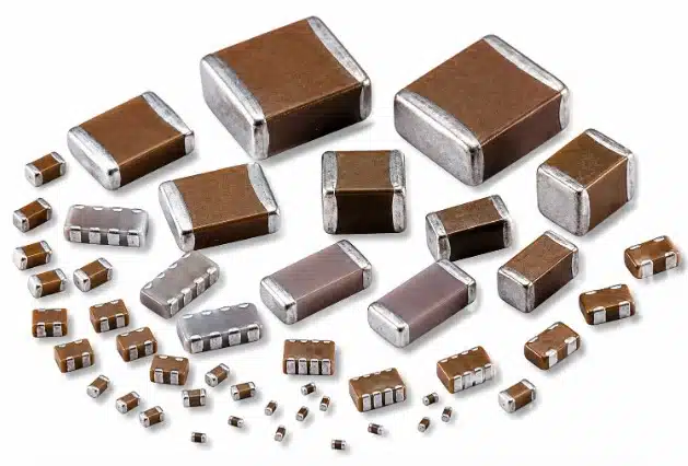
Larger package dimensions (such as 1206 or 1210 compared to 0402 or 0603) give the manufacturer room to use thicker dielectric layers (wider spacing between internal electrodes) for the same capacitance. Thicker layers mean a lower electric field per layer at a given voltage, which typically reduces DC bias sensitivity substantially[3][5].
Higher Voltage-Rated Parts
Selecting a component with a higher voltage rating for the same rail voltage—such as using a 50V-rated capacitor instead of a 25V capacitor on a 12V bus—often improves capacitance retention. A higher voltage rating places your operating point lower on the manufacturer’s DC bias curve, keeping your effective capacitance much closer to its nominal value. Confirm this on the actual curves, though: within the same case size and dielectric, some higher-voltage parts share essentially the same internal construction and show little or no improvement[3]. During BOM analysis, trading up in voltage rating or case size is often cheaper than redesigning a failing filter stage, because a capacitor’s true cost includes the rework, field failures, and redesign time a marginal part can trigger.
How to Read a DC Bias Curve and Use Manufacturer Simulation Tools
Never rely solely on text specifications when selecting Class 2 capacitors. Always inspect the manufacturer’s DC bias curve, which plots DC voltage against percentage capacitance change.
Because hand-calculating every operating point across a large BOM is inefficient, leading MLCC manufacturers provide robust online simulation software. Tools such as Murata SimSurfing[10], along with equivalent design platforms from TDK (SEAT and online characteristics viewer)[13], Samsung Electro-Mechanics (Component Library)[14], and KYOCERA AVX (SpiCAT/SpiMLCC)[15], plus KEMET K-SIM[16], allow you to input your exact part number, operating voltage, AC ripple, and temperature. These simulators generate effective capacitance curves from the manufacturer’s characterization data. Always verify current tool names and web links directly with the component manufacturer before final sign-off.
MLCC Derating Checklist for Your BOM
Before releasing your schematic and bill of materials to mass production, run through this quick verification checklist:
- Identify Dielectric Types: Separate Class 1 (C0G) and Class 2 (X5R/X7R) MLCC capacitors on your BOM, since these MLCC capacitor types respond to DC bias very differently.
- Check DC Bias Curves: Pull simulation data from the manufacturer for every Class 2 rail application, and confirm parts come from traceable sources so the curves you checked match the parts you receive.
- Verify Effective Capacitance: Ensure minimum usable capacitance meets circuit requirements at maximum operating voltage.
- Apply Voltage Headroom: Ensure operating voltages adhere to your target reliability class (typically operating at 50% to 80% of rated voltage).
- Qualifying Drop-In Replacements: When evaluating alternate parts during component shortages, always re-check the DC bias curves of substitute components. Minor package or manufacturer variations can drastically alter effective capacitance, and with MLCC lead times and prices rising, those substitutions are becoming more common.
Need Help Optimizing Your BOM for Reliability?
Navigating component derating, mitigating supply chain shortages, and securing hard-to-find passive components doesn’t have to slow down your product timeline. Partner with Suntsu for expert engineering support and global sourcing solutions.
Whether you need higher-voltage parts, larger case sizes, or qualified drop-in replacements, Suntsu can source the MLCCs your BOM calls for.
FAQs
You get two problems: the capacitor wears out faster, and it gives your circuit less capacitance than you planned for. On the reliability side, applied voltage speeds up dielectric wear. TDK’s life calculations treat it as a core stress factor: Voltage Acceleration is one of the two Acceleration Factors used to calculate FIT and MTBF[1]. NASA’s HALST research on base-metal-electrode MLCCs found that catastrophic failures follows the conventional power law with respect to stress[2], so a small increase in voltage can shorten life by a lot. That’s why NASA Goddard’s guideline sets capacitors at a Max. of 60% of rated voltage[11]. On the performance side, a Class 2 part run near its rating can lose most of its capacitance. That can lead to excess ripple, regulator instability or resets that only show up in testing or in the field. Heat makes both problems worse: TDK warns that running an MLCC past its temperature limit leads not only to lowered capacitance, but also to accelerated life deterioration, and in the worst case, short-circuit failure.
For capacitance loss, no. Murata states that the temperature compensation type of capacitors (C0G, etc.) have no DC bias characteristic[4], and KEMET describes C0G as a dielectric that exhibits no change in capacitance with respect to time and voltage. You don’t need to adjust a C0G’s value for bias or aging. For reliability, yes: voltage headroom still protects any capacitor against surges, transients and long-term wear. NASA’s guideline applies its 60% limit to capacitors in general, not only to Class 2 types[11]. Follow your program’s derating standard for C0G parts the same way you would for X7R.
It depends heavily on the part. KEMET notes that one MLCC may lose 10% capacitance at rated voltage while another MLCC of the same case size may lose 90% at rated voltage [5]. Small, high-value parts are the worst. In Analog Devices’ example, a 4.7µF, 6.3V capacitor in an 0603 package lost a lot even below its rating: At 5V the typical capacitance is 92.9% below nominal, or 0.33µF[3]. Larger case sizes, higher voltage ratings and Class 1 dielectrics lose much less. The only reliable figure for a specific part is the manufacturer’s DC bias curve, so check it in their simulation tool[10][13][14][15][16].
Voltage derating means running the capacitor below its rated voltage to protect its long-term reliability. TDK’s life models treat applied voltage as one of the two stresses that speed up dielectric wear, together with temperature: Voltage Acceleration is one of the two Acceleration Factors used to calculate FIT and MTBF[1][2]. Capacitance derating means working out how much capacitance the part actually gives you once DC bias, temperature and aging are applied. Class 2 parts can show a noticeable decrease in capacitance in some cases up to 90% at rated voltage[5]. A good design checks both.
Not always. A higher-rated part often keeps more capacitance at a given rail voltage, because you’re operating lower on its DC bias curve. But within the same case size and dielectric, some higher-voltage parts are built almost the same way inside and show little improvement[3]. Moving to a larger case size is usually the more dependable fix, because as the package size increases, the capacitance variation with applied DC voltage decreases, and substantially[3]. Either way, compare the actual curves before you commit.
Related Content
References
- TDK. “FIT and MTTF/MTBF (6): What factors affect the expected life and failure rates of MLCCs?” Available at: https://product.tdk.com/en/contact/faq/capacitors-0106.html
- D. Liu, NASA GSFC. “Highly Accelerated Life Stress Testing (HALST) of Base-Metal Electrode Multilayer Ceramic Capacitors” Available at: https://nepp.nasa.gov/files/24300/CARTS2013_Liu_HALST.pdf
- Analog Devices. “Temperature and Voltage Variation of Ceramic Capacitors, or Why Your 4.7µF Capacitor Becomes a 0.33µF Capacitor” Available at: https://www.analog.com/en/resources/technical-articles/temperature-and-voltage-variation-ceramic-capacitor.html
- Murata. “Does the capacitance change when a DC voltage is applied to ceramic capacitors?” Available at: https://www.murata.com/en-us/support/faqs/products/capacitor/mlcc/char/0005
- YAGEO Group (KEMET). “VCC: Capacitance Change vs Voltage in Ceramic Capacitors” Available at: https://www.mouser.lt/pdfDocs/Capacitance_Change.pdff
- KEMET. “Here’s What Makes MLCC Dielectrics Different” Available at: https://web.archive.org/web/20250126125105/https://www.kemet.com/en/us/technical-resources/heres-what-makes-mlcc-dielectrics-different.html
- Würth Elektronik. “Application Note SN011” Available at: https://www.we-online.com/components/media/o189880v410 SN011c EN.pdf
- EDN Asia. “Can you trust Class 2 ceramic capacitors?” Available at: https://www.ednasia.com/?p=23935
- A. Awalt, DigiKey. “Multilayer Ceramic Capacitors (MLCCs)” Available at: https://www.digikey.com/en/articles/multilayer-ceramic-capacitors-mlccs
- Murata. “What is the allowable ripple current Murata’s ceramic capacitors can withstand?” Available at: https://www.murata.com/en-us/support/faqs/products/capacitor/mlcc/char/0001
- NASA. “EEE Parts Derating” Available at: https://extapps.ksc.nasa.gov/Reliability/Documents/Preferred_Practices/1201.pdf
- A. Teverovsky. “Guidelines for Selection, Screening and Qualification of Low-Voltage Commercial Multilayer Ceramic Capacitors for Space Programs” Available at: https://nepp.nasa.gov/files/23923/Guidelines for selection of MLCCs rev.A.pdf
- TDK. “Dynamic DC Bias Model for accurate circuit simulation” Available at: https://www.tdk.com/en/news_center/press/201407081367.html
- Samsung Electro-Mechanics. “[Website Functionality Improvement] Now launching a graph tool-tip service that shows accurate data” Available at: https://www.samsungsem.com/global/newsroom/news/view.do?id=1481
- Mouser Electronics. “KYOCERA AVX SpiCAT Online Simulation Tool” Available at: https://www.mouser.sg/new/avx/avx-spicat-online-simulation-tool/
- Mouser Electronics. “KEMET K-SIM Simulation Tool” Available at: https://www.mouser.com/kemet-ksim-simulation-tool/
- KEMET. “Ceramic Capacitor Basics” Available at: https://www.digikey.be/en/ptm/k/kemet/ceramic-capacitor-basics/tutorial?slide=17