

Spot Buy: SK Hynix 16GB & 32GB eMMC, 4GB LPDDR4x In Stock

An exclusive inventory spot buy of brand-new SK Hynix memory components offers quick relief for hardware teams dealing with long lead times and component shortages. This specific release features 160,000 units of 16GB eMMC, 107,000 units of 32GB eMMC, and 140,000 units of 4GB (32Gb) LPDDR4x SDRAM, all carrying 2025 production date codes.

The teams this inventory helps are usually specific: a board already laid out around a 153-ball eMMC footprint, a build slot that will not move, and an allocation that

has just slipped. Requalifying a different package is expensive; sourcing the same part through a second channel is not.

An exclusive inventory spot buy of brand-new SK Hynix memory components offers quick relief for hardware teams dealing with long lead times and component shortages. This specific release features 160,000 units of 16GB eMMC, 107,000 units of 32GB eMMC, and 140,000 units of 4GB (32Gb) LPDDR4x SDRAM, all carrying 2025 production date codes.

The teams this inventory helps are usually specific: a board already laid out around a 153-ball eMMC footprint, a build slot that will not move, and an allocation that has just slipped. Requalifying a different package is expensive; sourcing the same part through a second channel is not.

Key Takeaways

  • Spot buys of factory-fresh SK Hynix components bypass factory lead times and protect active production schedules from sudden allocation bottlenecks.
  • The 16GB and 32GB eMMC parts share an identical 153-ball, 11.5 × 13 × 0.8 mm footprint, and the dual-die 32GB part writes at twice the sequential speed of the 16GB[1].
  • Both eMMC devices are commercial temperature grade — rated −25°C to +85°C operating and −40°C to +85°C storage — rather than the −40°C industrial operating floor[1].
  • Multi-level cell NAND flash memory balances density, write endurance, and cost, and the controller reports consumed program/erase life through the Extended CSD register so hosts can track aging in the field[1].
  • Advanced low-power features in LPDDR4x SDRAM components optimize thermal management and battery performance in compact embedded systems.

In Stock Now: SK Hynix Memory Spot Buy

16GB eMMC 5.1 H26M51002KPR

MLC eMMC with HS400 support in a 153-ball, 11.5 × 13 mm FBGA. Reads at 250 MB/s, for designs that need reliable onboard storage.
160,000 units in stock

32GB eMMC 5.1 H26M62002JPR

Same footprint and pinout as the 16GB part, so moving up in capacity needs no board changes. The dual-die design doubles write speed to 90 MB/s.
107,000 units in stock

4GB LPDDR4x SDRAM H9HCNNNCPMMLXR-NEE

Low-power LPDDR4x rated to 4266 Mbps in a 200-ball FBGA. Its 0.6V I/O rail reduces bus power in battery-powered and compact designs.
140,000 units in stock

What Are the Core Architectural Specifications and Interface Speeds for the eMMC Options?
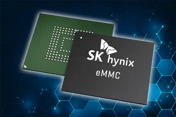
The 16GB eMMC (part number H26M51002KPR) and 32GB eMMC (part number H26M62002JPR) both comply with the JEDEC eMMC 5.1 specification (JESD84-B51) and remain backward compatible with eMMC 4.5 and 5.0[1]. Embedded MultiMediaCard (eMMC) combines flash storage and a managed NAND controller within a single ball grid array package, handling wear leveling and error correction code management independently of the host processor. Both components use multi-level cell (MLC) NAND flash memory, which stores two bits per cell, balancing storage capacity with

endurance.

HS400 provides a 400 MB/s bus ceiling over a 200 MHz DDR clock, available only on an 8-bit bus at 1.8V VCCQ[1][4]. That 400 MB/s figure is the interface ceiling rather than device throughput. Measured at device level over HS400, the 16GB part reads sequentially at 250 MB/s and writes at 45 MB/s, while the 32GB part — built from two stacked 128Gb dies — reads at 280 MB/s and writes at 90 MB/s[1]. That write-speed gap is the detail to check against a data-logging duty cycle, since the 32GB part’s second die doubles write throughput, not just capacity.

Speed mode is selected by the host during initialization rather than negotiated on the fly, and the specification does not permit a direct switch from HS200 to HS400; the host must pass through DDR52 first[1]. Hosts implementing Enhanced Strobe can reach HS400 without running the tuning procedure at all.

Both parts take a 2.7–3.6V VCC rail for the NAND array and a 1.7–1.95V VCCQ rail for the controller and interface. A 3.3V VCCQ option is not offered on this family, so a host designed around a 3.3V eMMC I/O rail cannot use these devices[1]. Engineers exploring alternative storage solutions are advised to consult the broader flash memory catalog or consider specialized options available in the eMMC category.

The 16GB eMMC (part number H26M51002KPR) and 32GB eMMC (part number H26M62002JPR) both comply with the JEDEC eMMC 5.1 specification (JESD84-B51) and remain backward compatible with eMMC 4.5 and 5.0[1]. Embedded MultiMediaCard (eMMC) combines flash storage and a managed NAND controller within a single ball grid array package, handling wear leveling and error correction code management independently of the host processor. Both components use multi-level cell (MLC) NAND flash memory, which stores two bits per cell, balancing storage capacity with endurance.

HS400 provides a 400 MB/s bus ceiling over a 200 MHz DDR clock, available only on an 8-bit bus at 1.8V VCCQ[1][4]. That 400 MB/s figure is the interface ceiling rather than device throughput. Measured at device level over HS400, the 16GB part reads sequentially at 250 MB/s and writes at 45 MB/s, while the 32GB part — built from two stacked 128Gb dies — reads at 280 MB/s and writes at 90 MB/s[1]. That write-speed gap is the detail to check against a data-logging duty cycle, since the 32GB part’s second die doubles write throughput, not just capacity.

Speed mode is selected by the host during initialization rather than negotiated on the fly, and the specification does not permit a direct switch from HS200 to HS400; the host must pass through DDR52 first[1]. Hosts implementing Enhanced Strobe can reach HS400 without running the tuning procedure at all.

Both parts take a 2.7–3.6V VCC rail for the NAND array and a 1.7–1.95V VCCQ rail for the controller and interface. A 3.3V VCCQ option is not offered on this family, so a host designed around a 3.3V eMMC I/O rail cannot use these devices[1]. Engineers exploring alternative storage solutions are advised to consult the broader flash memory catalog or consider specialized options available in the eMMC category.

Part NumberTypeDensityUsable CapacityPackageSequential Read/WriteVoltageOperating Temperature
H26M51002KPR[1]eMMC 5.1, MLC, 128Gb x 116GB14.68GB153-ball FBGA, 11.5 × 13 × 0.8 mm250 / 45 MB/sVCC 2.7–3.6V, VCCQ 1.7–1.95V−25°C to +85°C
H26M62002JPR[1]eMMC 5.1, MLC, 128Gb x 232GB29.12GB153-ball FBGA, 11.5 × 13 × 0.8 mm280 / 90 MB/sVCC 2.7–3.6V, VCCQ 1.7–1.95V−25°C to +85°C
H9HCNNNCPMMLXR-NEE[5]LPDDR4x SDRAM4GB(32Gb)-200-ball FBGA4266 MbpsVDD1 1.8V / VDD2 1.1V / VDDQ 0.6V−25°C to +85°C

Are the Package Footprints Compatible Between the 16GB and 32GB eMMC Parts for Scalable Board Designs?

The 16GB (H26M51002KPR) and 32GB (H26M62002JPR) variants are physically compatible, enabling hardware engineers to create scalable printed circuit boards without needing layout changes. Both use the same 153-ball fine-pitch BGA outline, 11.5 × 13 × 0.8 mm, on a 0.5 mm ball pitch with identical ball assignments[1]. This interchangeability allows product developers to incorporate multiple storage options on a single baseboard.

The host still sees a different device: sector count, device version and CID product name all change with density, so the bootloader and partition layout need to account for the larger part even though the board does not. Usable capacity is lower than the marketed density in both cases: the 16GB part presents 14.68GB to the host and the 32GB part presents 29.12GB, with the balance reserved for NAND management and maintenance[1]. Boot partition sizes are identical across both densities at 4MB each, with a 16MB RPMB partition.

Access to these flexible components via independent distribution channels helps keep manufacturing lines running smoothly, even if factory allocations shift. Teams can also explore a wide range of inventory options by consulting the main integrated circuits index.

What Performance Metrics and Low-Power Characteristics Distinguish the LPDDR4x Component?
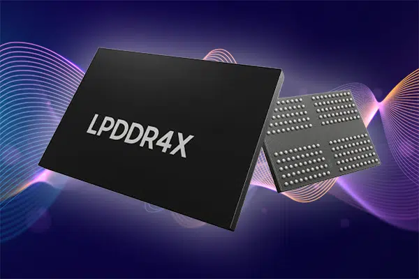
The 4GB (32Gb) LPDDR4x SDRAM, part number H9HCNNNCPMMLXR-NEE, delivers high bandwidth at low power in a 200-ball FBGA, rated to 4266 Mbps and specified from −25°C to +85°C[5]. JEDEC published LPDDR4X as Addendum No. 1 to JESD209-4, and the defining change is the I/O supply: VDDQ drops from the 1.1V used by LPDDR4 to 0.6V, a 40% reduction that cuts the energy spent driving data across the bus on both the memory and the controller side[2][3]. The core rails are unchanged at VDD1 1.8V and VDD2 1.1V[5] — worth stating explicitly, since distributor listings for this part often

quote only the 1.1V VDD2 figure. Alongside the lower I/O voltage, the device offers low-power states that extend battery life in portable or remote systems. Engineers comparing alternatives can review the broader DRAM memory range. Hardware designers often pair these modules with sophisticated power management ICs to optimize performance and efficiency. Ensuring a reliable supply of these high-performance parts helps avoid delays caused by typical component shortages.

The 4GB (32Gb) LPDDR4x SDRAM, part number H9HCNNNCPMMLXR-NEE, delivers high bandwidth at low power in a 200-ball FBGA, rated to 4266 Mbps and specified from −25°C to +85°C[5]. JEDEC published LPDDR4X as Addendum No. 1 to JESD209-4, and the defining change is the I/O supply: VDDQ drops from the 1.1V used by LPDDR4 to 0.6V, a 40% reduction that cuts the energy spent driving data across the bus on both the memory and the controller side[2][3]. The core rails are unchanged at VDD1 1.8V and VDD2 1.1V[5] — worth stating explicitly, since distributor listings for this part often quote only the 1.1V VDD2 figure. Alongside the lower I/O voltage, the device offers low-power states that extend battery life in portable or remote systems. Engineers comparing alternatives can review the broader DRAM memory range. Hardware designers often pair these modules with sophisticated power management ICs to optimize performance and efficiency. Ensuring a reliable supply of these high-performance parts helps avoid delays caused by typical component shortages.

How Do These MLC-Based eMMC Devices Perform in Commercial and Light-Industrial Operating Environments?

Both eMMC devices are specified for operation from −25°C to +85°C ambient, with a −40°C to +85°C non-operating storage range[1]. That is a commercial grade rather than the −40°C industrial operating floor, and the distinction matters: the storage range is genuinely useful for shipping and warehousing, but a design that must power up below −25°C needs SK hynix’s IT- or AAT-grade e-NAND part numbers instead. Within that range, the embedded controller handles wear levelling, bad block management, garbage collection and error correction independently of the host processor, and protects stored data against an unexpected host power-off[1].

  • Controller-managed bad block management isolates failing memory blocks automatically to protect system integrity over years of continuous operation.
  • Error correction engines correct bit errors introduced by read disturb or environmental stress, up to the controller’s correction strength.
  • On-die health reporting exposes consumed program/erase life and pre-EOL warnings through the Extended CSD register, so a host can flag an ageing device before it fails rather than after[1].
  • Part of the user area can be configured as enhanced storage in SLC mode for higher-endurance boot or log partitions, at a 2:1 capacity cost against the default MLC area[1].

Procurement professionals handling bills of materials for harsh environments can optimize their component sourcing by using specialized BOM analysis and cost reduction services. Independently sourced parts should be inspected to AS6081, the counterfeit-avoidance standard written for exactly this channel. Ensuring high reliability early on safeguards end products against field failures and costly warranty claims.

What Advantages Do Fresh 2025 Production Date Codes Offer for Manufacturing and Long-Term Reliability?

Recent production date codes reduce some of the risks that accumulate in long-held inventory, most notably solder ball oxidation. Stock held in unverified conditions can accumulate solder-ball oxidation, which drives head-in-pillow (ball-and-socket) defects — where the ball and the paste both reflow but never merge into a single joint. Because the joint sits under the package, these pass visual inspection and surface later as intermittent faults, requiring X-ray to detect.

  • Recent production means less elapsed time between manufacture and reflow, reducing cumulative exposure risk to the solderable surfaces.
  • Both eMMC devices are RoHS compliant as a product attribute, independent of date code[1]. REACH declarations are supplied on request and sourced against the SVHC candidate list in force at the time of shipment.

Handling requirements are set by IPC/JEDEC J-STD-033, which ties dry-pack

shelf life to the bag seal date rather than the component date code, with the humidity indicator card as the deciding check at goods-in[6]. Recent production improves the odds of an intact bag with live desiccant and a short interval since seal, but the seal date, HIC reading and MSL rating are what determine whether a bake is required[6][7].

Adding new components to your assembly lines boosts first-pass yield and minimizes manufacturing issues. Collaborating with a trusted supply chain specialist helps ensure all parts comply with strict quality standards before arriving at your production floor. You can examine the quality assurance process to see how separate channels confirm the quality of incoming inventory.

Recent production date codes reduce some of the risks that accumulate in long-held inventory, most notably solder ball oxidation. Stock held in unverified conditions can accumulate solder-ball oxidation, which drives head-in-pillow (ball-and-socket) defects — where the ball and the paste both reflow but never merge into a single joint. Because the joint sits under the package, these pass visual inspection and surface later as intermittent faults, requiring X-ray to detect.

  • Recent production means less elapsed time between manufacture and reflow, reducing cumulative exposure risk to the solderable surfaces.
  • Both eMMC devices are RoHS compliant as a product attribute, independent of date code[1]. REACH declarations are supplied on request and sourced against the SVHC candidate list in force at the time of shipment.

Handling requirements are set by IPC/JEDEC J-STD-033, which ties dry-pack shelf life to the bag seal date rather than the component date code, with the humidity indicator card as the deciding check at goods-in[6]. Recent production improves the odds of an intact bag with live desiccant and a short interval since seal, but the seal date, HIC reading and MSL rating are what determine whether a bake is required[6][7].

Adding new components to your assembly lines boosts first-pass yield and minimizes manufacturing issues. Collaborating with a trusted supply chain specialist helps ensure all parts comply with strict quality standards before arriving at your production floor. You can examine the quality assurance process to see how separate channels confirm the quality of incoming inventory.

Secure Your Memory Allocation Today

This spot buy covers three SK Hynix parts, all carrying 2025 date codes: 160,000 units of the 16GB H26M51002KPR eMMC, 107,000 units of the 32GB H26M62002JPR eMMC, and 140,000 units of the 4GB H9HCNNNCPMMLXR-NEE LPDDR4x SDRAM. Both eMMC parts are covered by the SK hynix e-NAND datasheet, and full specifications for the LPDDR4x are in the SK hynix LPDDR4X datasheet.

Quantities are limited to the inventory listed above. Suntsu offers quick access to verified spot-buy stock, so your production schedule doesn’t have to wait on factory lead times.

Secure your memory component allocation today and protect your production schedule from unexpected lead-time extensions. Contact the Suntsu team to request a quote on these factory-fresh SK Hynix parts.

FAQs

Yes. eMMC 5.1 devices are backward compatible with slower bus modes, including HS200 (200 MB/s), DDR52 (104 MB/s), and High Speed SDR (52 MB/s), as well as 4-bit and 1-bit bus widths. The device runs at the fastest mode both it and the processor support. On an HS200 host, sequential reads are capped at about 200 MB/s instead of the 250–280 MB/s these parts reach over HS400. Write speeds of 45 and 90 MB/s are unaffected because they’re already below that limit.

Yes. Most embedded processors can load their bootloader from eMMC. Depending on the processor’s boot ROM, it loads from one of the two dedicated boot partitions or from the main user area. The active boot partition is selected in the BOOT_PARTITION_CONFIG register (EXT_CSD byte 179), which Linux users can set with mmc-utils. Each boot partition is 4MB, which holds most bootloaders, but larger boot images may need to go in the user area.

No. eMMC is a JEDEC-standard interface, so the Linux MMC subsystem, which Android also uses, supports these devices without a part-specific driver. What matters is your processor’s host controller driver and board configuration. HS400, for example, must be supported by the host controller and enabled in the device tree with properties like mmc-hs400-1_8v or mmc-hs400-enhanced-strobe. The LPDDR4x needs no operating system driver either, but it does need memory setup and training code in the bootloader. That code usually comes from the processor vendor’s board support package.

Several eMMC settings can only be written once, so test them on sample parts before production:

  • Partition layout: general-purpose partitions and the enhanced (SLC-mode) user area lock once the PARTITION_SETTING_COMPLETED flag is set.
  • Hardware reset pin: the RST_n pin is ignored by default, and enabling or disabling it in EXT_CSD byte 162 is permanent. Boards that depend on a hardware reset line need this set on purpose.
  • Permanent write protection: once applied to a boot partition or part of the user area, it can’t be removed.
  • RPMB key: the authentication key can only be programmed once.

The Replay Protected Memory Block (RPMB) is a small secure area of the eMMC, 16MB on these parts, that only accepts authenticated writes. Each write is signed with an HMAC-SHA256 key shared between the host and the device. A write counter stops attackers from replaying old messages. Common uses include encryption keys, secure boot state, and anti-rollback counters, often managed through a trusted execution environment such as OP-TEE. The key can’t be read back or changed after it’s programmed, so key provisioning should happen in a controlled manufacturing step.

References

  1. SK Hynix. “e-NAND Product Family, eMMC5.1 Compatible” Available at: https://suntsu.com/wp-content/uploads/2026/09/H26M51002KPR.pdf
  2. JEDEC. “Low Power Memory: LPDDR” Available at: https://www.jedec.org/category/technology-focus-area/mobile-memory-lpddr-wide-io-memory-mcp
  3. JEDEC. “JEDEC Updates Standards for Low Power Memory Devices” Available at: https://www.jedec.org/news/pressreleases/jedec-updates-standards-low-power-memory-devices-0
  4. JEDEC. “JEDEC Announces Publication of e.MMC Standard Update v5.0” Available at: https://www.jedec.org/news/pressreleases/jedec-announces-publication-emmc-standard-update-v50
  5. SK Hynix. “DRAM – LPDDR  Products” Available at: https://suntsu.com/wp-content/uploads/2026/09/H9HCNNNCPMMLXR-NEE_Datasheet.pdf
  6. IPC/JEDEC. “J-STD-033B.1 — Handling, Packing, Shipping and Use of Moisture/Reflow Sensitive Surface Mount Devices” Available at: https://www.surfacemountprocess.com/uploads/5/4/1/9/54196839/j-std-033b01.pdf
  7. JEDEC. “JEP113 — Symbol and Labels for Moisture-Sensitive Devices” Available at: https://www.navsea.navy.mil/Portals/103/Documents/NSWC_Crane/SD-18/Test Methods/jep113b.pdf

keyboard_arrow_up