Resistors come in many forms. Some are as simple as a coil of wire made of material that is a poor conductor, such as powdered carbon. Other poor conducive materials include carbon composition, carbon film, metal film, and wirewound. Low noise circuits will always use low resistor values and low voltage wherever possible. Resistors normally have 1%, 2%, 5%, and 10% of tolerance. Keep in mind, resistors can have inductance.
A potentiometer is considered a variable resistor that can be adjusted to increase or decrease resistance depending on which of the three terminals is selected. There is also a photo resistor (photocell). A photo resistor when exposed to light, its resistance decreases, in turn making it an excellent light sensor.
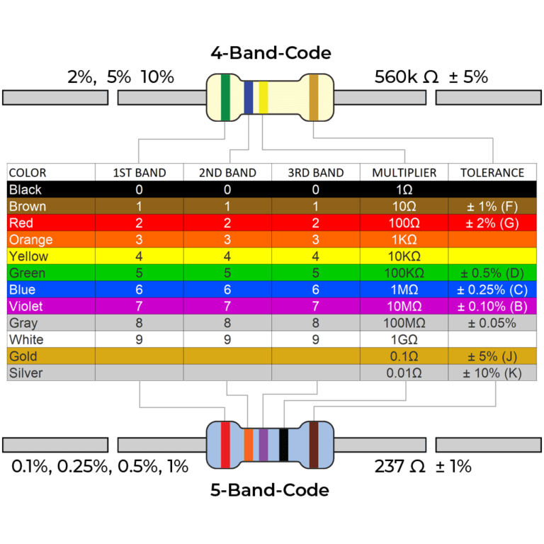
To use Suntsu’s Resistor Color Code, first you must know how to read it. First and foremost, color bands are used to read values of resistors. Printed numbers would be too small to read. Bands on a resistors are “grouped” meaning the gaps between them are not equal. The larger gap is placed before the tolerance band. So, you will place the bigger gap on the left and read from left to right. Oftentimes, the tolerance resistor is marked a metallic color: gold, and silver, respectively. One thing to note, a resistor code never starts with the metallic gold and silver. If you see those colors, it is the tolerance value and needs to be placed on the right side and continue to read it from left to right.
The value of resistance is marked by this color chart below:

 Black 0
 Brown 1
 Red 2
Red 2 Orange 3
 Yellow 4
 Green 5
 Blue 6
 Violet 7
 Gray 8
 White 9
 Brown 100 ppm
 Red 50 ppm
 Orange 15 ppm
 Yellow 25 ppm
 Blue 10 ppm
 Violet 5 ppm
 Gold
Gold  Silver